Continue to Site

Welcome to EDAboard.com

Welcome to our site! EDAboard.com is an international Electronics Discussion Forum focused on EDA software, circuits, schematics, books, theory, papers, asic, pld, 8051, DSP, Network, RF, Analog Design, PCB, Service Manuals... and a whole lot more! To participate you need to register. Registration is free. Click here to register now.

How to determine the stability of a CL-sys from BODE plots

Status
Not open for further replies.

powersys

Advanced Member level 1
Joined
Nov 29, 2005
Messages
439
Helped
3
Reputation
6
Reaction score
2
Trophy points
1,298
Activity points
4,981
bode plot cross frequency

Bode plots:
1) Magnitude vs frequency
2) Phase vs frequency

How do we determine, from BODE plots, that a system is stable or not?

Revised Bode Stability Criterion
**broken link removed**
 

bode plot stability

Hi,
You must calculate the Phase Margin aand the Gain Margin. By calculating these you can see if the system is staible.
If the Phase Margin becomes "-" that means the system is not stable.
 

    powersys

    Points: 2
    Helpful Answer Positive Rating
determine phase and gain margin of bode plot

medsalehi said:
Hi,
You must calculate the Phase Margin aand the Gain Margin. By calculating these you can see if the system is staible.
If the Phase Margin becomes "-" that means the system is not stable.

What if the Gain Margin becomes "-", but Phase Margin is still "+", is the closed-loop system stable?


This online tutorial (**broken link removed**) states that:
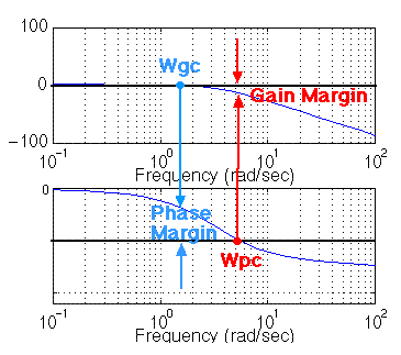
If the gain cross over frequency is less than the phase cross over frequency(i.e. Wgc < Wpc), then the closed-loop system will be stable.
Can this definition be applied in every case?

59_1182835290.gif
 

stability of bode plot based on gm and pm

we all say negtive feedback stablility . that's why we check the phase @ gain=0 db. if this rule is violated, that's mean your feedback will enhance the input, system will unstable. gain margin is the same we need to check the gain@phase=180 . just think system have any frequency input but we want it stable. for those input,which frequency will lead to phase larger than 180 we want it feedback mag less than 1 (0db).
for the positive feedback . the stable condistion is gain <1 (0db) one example is the constant gm bias circuit
 

    powersys

    Points: 2
    Helpful Answer Positive Rating
how to determine the stability of the system

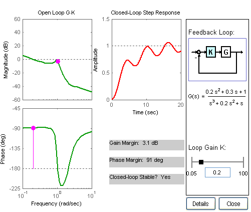
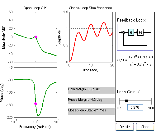
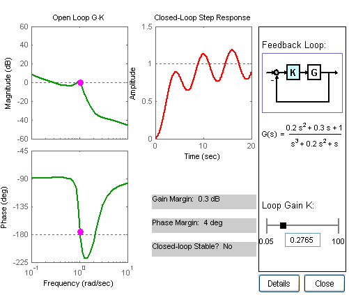
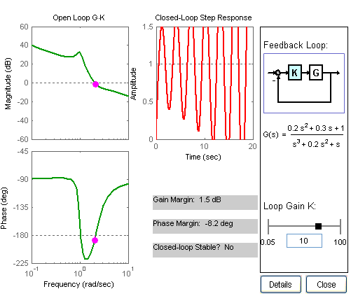
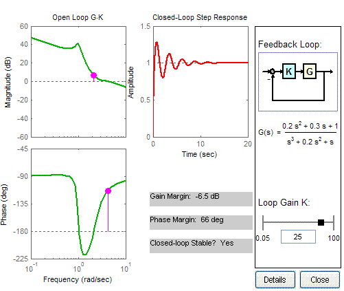
By varying the value K in 'margindemo.m' of MATLAB, the system behaviour changes as follows:

23_1182838884.gif


48_1182839083.gif


12_1182839097.gif


78_1182839113.gif


23_1182839129.gif


Added after 17 minutes:

ramberwang said:
we all say negtive feedback stablility . that's why we check the phase @ gain=0 db. if this rule is violated, that's mean your feedback will enhance the input, system will unstable. gain margin is the same we need to check the gain @ phase=180. just think system have any frequency input but we want it stable. for those input, which frequency will lead to phase larger than 180 we want it feedback mag less than 1 (0db).
for the positive feedback . the stable condistion is gain <1 (0db) one example is the constant gm bias circuit
Thanks you reply... I like your comments as I always ask myself why gain margin must be determined at wpc = -180 deg, and why phase margin must be determined at wgc = 0 dB. However, I still don't really see the points yet. I would be very appreciate if you could elaborate or give more examples. Thanks in advance.

By the way, if you refer to the images captured from 'margindemo.m' of Matlab (see above), we find out, when:
K = 0.2000 --> GM = '+' --> PM = '+' --> stable
K = 0.2760 --> GM = '+' --> PM = '+' --> stable
K = 0.2765 --> GM = '+' --> PM = '+' --> NOT stable
K = 10.0000 --> GM = '+' --> PM = '-' --> NOT stable
K = 20.0000 --> GM = '-' --> PM = '+' --> stable

I found out the system can be stable or not stable when the PM is '+' or '-'. Therefore, how to determine the stability of a closed-loop system from Bode plots of the open-loop transfer function of the system? Pls advise.

Added after 12 minutes:

Some says:
1) If GM = '+' and PM = '+', then the closed loop system is stable. Or,
2) If PM = '-', then the closed loop system is NOT stable. Or,
3) If wgc < wpc, then the closed loop system is stable.

But if we refer to the images from 'margindemo.m' of Matlab, none of the cases (1, 2, or 3) can explain correctly. Therefore, really need advise on how to determine the relative stability from Bode plots.

Added after 20 minutes:

The following paper has another definition:
A note on stability analysis using Bode plots ( **broken link removed** ) states:
Revised Bode Stability Criterion
A closed-loop system is stable if the open-loop system is stable and the frequency response of the open-loop transfer function has an amplitude ratio of less than unity at all frequencies corresponding to Φ = -180 deg - n*360 deg, where n = 0, 1, 2,..., ∞.
What does "amplitude ratio of less than unity" mean? Pls advise.
 

bode plots enhance feedback analysis pdf

As documents you ploted said. :
A system should only be analyzed for
stability using the Bode plot, if it has at most
one phase crossover frequency. Additionally,
if it has only one gain crossover frequency
and the amplitude ratio as well as the phase
angle are decreasing at the gain crossover
and afterward, then the gain and phase
margins can be calculated in a way found in
control textbooks.


From my experience. In practice. Though the phase curve pass 180 one time, have good phase margin. but system is unstable. because some zero could be introduced to give you some 'fake' phase margin. the best method to check system method is run transient simulation.
 

bode plots enhance feeback

ramberwang said:
As documents you ploted said. :
A system should only be analyzed for
stability using the Bode plot, if it has at most
one phase crossover frequency. Additionally,
if it has only one gain crossover frequency
and the amplitude ratio as well as the phase
angle are decreasing at the gain crossover
and afterward, then the gain and phase
margins can be calculated in a way found in
control textbooks.

From my experience. In practice. Though the phase curve pass 180 one time, have good phase margin. but system is unstable. because some zero could be introduced to give you some 'fake' phase margin. the best method to check system method is run transient simulation.
Therefore, Bode plot is not a 'safe' tool for determing the relative stability, can I say like that?

Thanks
 

determine controller constant bode plot

Hi,
you must calculate Phase Margine (180-phase(@gain=0dB))
it must be larger than 45
 

hey friend i have one doubt ahy phase margine should be grateer than 45 deg for stability?
is there any mathematical proof for that !!!!!!
If there is any math calculation, please let me know..
thank u
 

Re: How to determine the stability of a CL-sys from BODE plo

kalaianand said:
hey friend i have one doubt ahy phase margine should be grateer than 45 deg for stability?
is there any mathematical proof for that !!!!!!
If there is any math calculation, please let me know..
thank u

If the phase margin is positive (for example: +5 deg.) the system is stable - that means the step response exhibits a decaying oscillation. However, this margin is in practice too small because of uncertainties in the system. More than that, such a step response cannot be accepted for an amplifier. Thus, a phase margin - if possible - of app. 60...65 deg is wanted. 45 deg. is an absolute minimum (because of the step response, not because of stability problems).

However, it must be noted that the above rule is the result of the simplified Nyquist stability criterion and applies only
if both the magnitude and the phase response cross the zero-db or zero-deg lines, respectively, only once.

If this is not the case, the complete Nyquist criterion has to be applied.

Added after 26 minutes:

To complete the requirements for Bode stability analysis: The system must be a minimum-phase system (no allpass elements).
 

Re: stability of bode plot based on gm and pm

i need to know
if we have large gain crossover frequency while all other parameters (phase margin, overshoot, setling time and steady state error) are quite good , then what's the disadvantage of greater gain crossover frequency???
 

Re: how to determine the stability of the system

By varying the value K in 'margindemo.m' of MATLAB, the system behaviour changes as follows:

23_1182838884.gif


48_1182839083.gif


12_1182839097.gif


78_1182839113.gif


23_1182839129.gif


Added after 17 minutes:


Thanks you reply... I like your comments as I always ask myself why gain margin must be determined at wpc = -180 deg, and why phase margin must be determined at wgc = 0 dB. However, I still don't really see the points yet. I would be very appreciate if you could elaborate or give more examples. Thanks in advance.

By the way, if you refer to the images captured from 'margindemo.m' of Matlab (see above), we find out, when:
K = 0.2000 --> GM = '+' --> PM = '+' --> stable
K = 0.2760 --> GM = '+' --> PM = '+' --> stable
K = 0.2765 --> GM = '+' --> PM = '+' --> NOT stable
K = 10.0000 --> GM = '+' --> PM = '-' --> NOT stable
K = 20.0000 --> GM = '-' --> PM = '+' --> stable

I found out the system can be stable or not stable when the PM is '+' or '-'. Therefore, how to determine the stability of a closed-loop system from Bode plots of the open-loop transfer function of the system? Pls advise.

Added after 12 minutes:

Some says:
1) If GM = '+' and PM = '+', then the closed loop system is stable. Or,
2) If PM = '-', then the closed loop system is NOT stable. Or,
3) If wgc < wpc, then the closed loop system is stable.

But if we refer to the images from 'margindemo.m' of Matlab, none of the cases (1, 2, or 3) can explain correctly. Therefore, really need advise on how to determine the relative stability from Bode plots.

Added after 20 minutes:

The following paper has another definition:
A note on stability analysis using Bode plots ( **broken link removed** ) states:

What does "amplitude ratio of less than unity" mean? Pls advise.

Hi Powersys,

I was wondering if margindemo.m is a system file or if you made it up? If you did could you put it up?

Cheers
karthick
 

how stability can be determined from wpc & wgc values

check the below link -


**broken link removed**
 

Re: How to determine the stability of a CL-sys from BODE plo

Can someone explain why some applicaitons notes regarding the AC-DC converter (constant current, LED driver) never mention the stability analysis?
I am amazed about that, and hopefully someone can give me some good explanations. Thanks.

If the phase margin is positive (for example: +5 deg.) the system is stable - that means the step response exhibits a decaying oscillation. However, this margin is in practice too small because of uncertainties in the system. More than that, such a step response cannot be accepted for an amplifier. Thus, a phase margin - if possible - of app. 60...65 deg is wanted. 45 deg. is an absolute minimum (because of the step response, not because of stability problems).

However, it must be noted that the above rule is the result of the simplified Nyquist stability criterion and applies only
if both the magnitude and the phase response cross the zero-db or zero-deg lines, respectively, only once.

If this is not the case, the complete Nyquist criterion has to be applied.

Added after 26 minutes:

To complete the requirements for Bode stability analysis: The system must be a minimum-phase system (no allpass elements).
 

Re: How to determine the stability of a CL-sys from BODE plo

Can someone explain why some applicaitons notes regarding the AC-DC converter (constant current, LED driver) never mention the stability analysis?
I am amazed about that, and hopefully someone can give me some good explanations. Thanks.

Perhaps because stability is not an issue? Can you explain, please, why you feel "amazed"?
 

Status
Not open for further replies.

Part and Inventory Search

Welcome to EDABoard.com

Sponsor

Back
Top