Continue to Site

Welcome to EDAboard.com

Welcome to our site! EDAboard.com is an international Electronics Discussion Forum focused on EDA software, circuits, schematics, books, theory, papers, asic, pld, 8051, DSP, Network, RF, Analog Design, PCB, Service Manuals... and a whole lot more! To participate you need to register. Registration is free. Click here to register now.

motor controlling PIC16f877A LM293

Status
Not open for further replies.

bazaria

Newbie level 5
Newbie level 5
Joined
Aug 29, 2006
Messages
8
Helped
1
Reputation
2
Reaction score
0
Trophy points
1,281
Activity points
1,374
pid ic

Hi,
I am looking for a single chip to control a motor. This chip should have 3 PWM outputs and an encoder inputs with programmable control rule.
I found all that in a single chip LM629 but I can't find a normal way to program it. May be you can direct me to some other chip that is more comfortable to work with?
 

pid controller ic

hi,

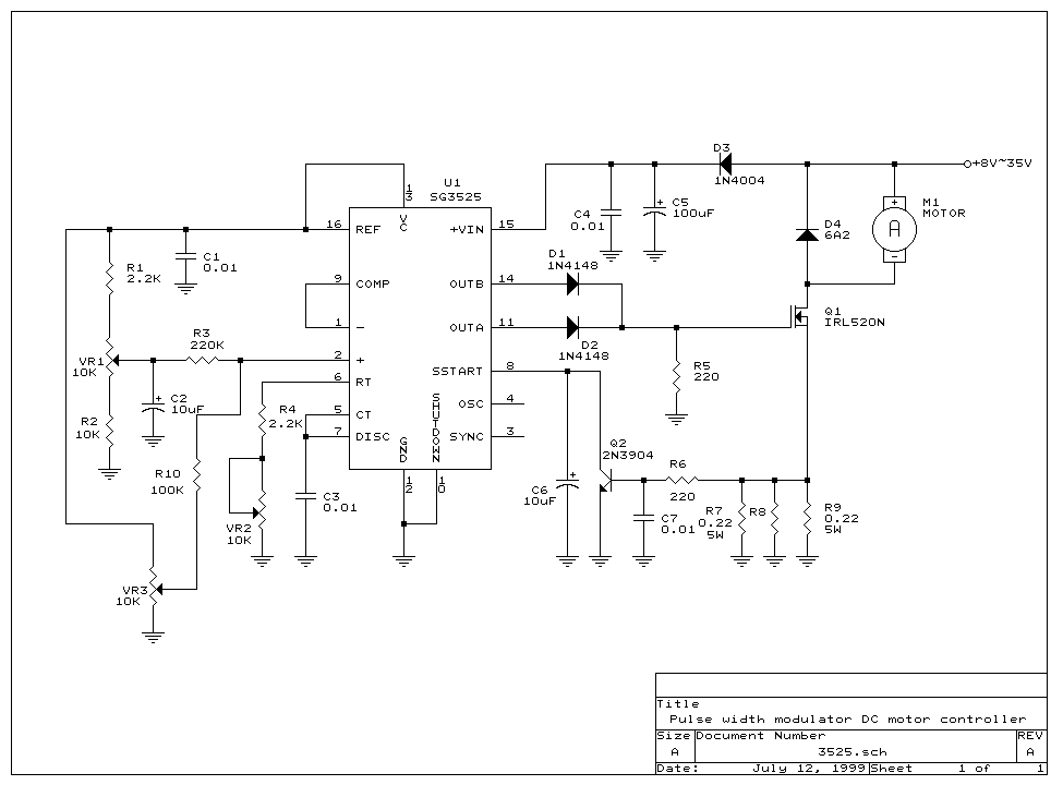
use the SG3525 IC for controlling the DC motor

62_1166798938.gif
 

mc3phac board

I have some useful expriences with Lm629 and LM628 and their programming and initializing are easy and straightforward. but as I remember it was for controlling Dc motor type not for 3 ph motors!!!!
you can use Mc3phac for controlling 3 phase ac motors from freescale.
check it out!
 

    V

    Points: 2
    Helpful Answer Positive Rating
operational amplifier pid encoder

The advantage of LM628 is in being capable of driving the motor and controling it's speed/position using an encoder feedback
I would appreciate any material regarding this device
 

    V

    Points: 2
    Helpful Answer Positive Rating
schematics pid motor

I want to know how to command lm629?

like I want to full speed or half speed?

and I afraid in my country this IC can't found....i want to where to buy it..?

thx for the information
 
lm675 applications

help me.. i need some example for programing lm628 with pic16f877a..
 

lm628 source

I have a bunch of assembler code I've written for DSPIC 33f256gp710 and DSPIC30F4011 that controls the LM628. If you're seriously interested, I'll convert to .pdf and post it. Some of the code runs the HCTL1100 motor controller too. I had attempted to upload it yesterday before realizing that .txt files won't upload.
 
  • Like
Reactions: capacitor22

    V

    Points: 2
    Helpful Answer Positive Rating

    capacitor22

    Points: 2
    Helpful Answer Positive Rating
lm629 timing forum

patweadock said:
I have a bunch of assembler code I've written for DSPIC 33f256gp710 and DSPIC30F4011 that controls the LM628. If you're seriously interested, I'll convert to .pdf and post it. Some of the code runs the HCTL1100 motor controller too. I had attempted to upload it yesterday before realizing that .txt files won't upload.

Nice stuff, I think if you can post it this can be very useful.

Thanks for your effort!

Bye
Pow
 
lm629 programmimg

patweadock said:
I have a bunch of assembler code I've written for DSPIC 33f256gp710 and DSPIC30F4011 that controls the LM628. If you're seriously interested, I'll convert to .pdf and post it. Some of the code runs the HCTL1100 motor controller too. I had attempted to upload it yesterday before realizing that .txt files won't upload.

can u upload program to control lm628 please.. thanx..
 
lm675

I have been trying to build an arm robot, but it's difficult to do with the parts I have available. I did build a CNC mill, good for making circuit boards, but the dremel tool that is it's cutter doesn't do well with aluminum. Thanks for your interest, please reply if you see anyway I might improve it. Pat
 

lm628 clock forum

Pat, thanx for the code.. it gave me some idea to program lm628.. i'm currently built a mobile robot to test encoder and precision motion controller.. i'm using pic basicpro and pic16f877a.. how u connect 6 Mhz crystal to lm628? i'm having trouble to read and write 2 byte pair at port d (lm628).. any suggestion..
 

lm628 code

I'm using an 8 MHz powered resonator, because I have lm628-8. Just put a cap (about 10nF) on each leg of the crystal, both caps going to ground, then connect one side of the crystal to the clock input. (I could send you an 6 MHz resonator if you can't fet one). You should have an LCD display and keypad connected to the microcontroller and working, before attempting to debug the motor control circuit.
 

lmd18200 atmega128 motor schematic

thanx for ur help pat.. :) i've bought lcd to debug my program.. it seem that my problem is to write 2 pair of data byte (16 bit to port d of lm628),how do i know that i've succeed to write that?

then another problem.. it is necessary to use 'power' op amp such as lm12 and lm675.. i found that those ic not sell at my place.. then i try normal op amp,lm324 but my motor did not run even though the output of op amp is 12v.. any solution pat..
 

lm675 application

What type of DAC are you using? You need to write one byte at a time to the lm628, then after writing two bytes, you need to check the busy bit (bit zero of the status byte) then wait for busy bit to go low before the code proceeds. You also need to check busy bit after writing an instruction. If you check the status byte, you can tell if the data was accepted by checking the "command error" bit #1. The 324 op amp won't provide enough current, you need a power op amp or a set of complimentary transistors in "push-pull" operation to provide at least a few hundred milliamps, depending on the motor and the torque required for your application. Can you obtain parts like these?
I looked at the datasheet for pic16f877, I understand you're using PortD for the LM628. What bits are you using for RD, WR, PS and Reset? Perhaps you could use PortB for the LCD and PortC for the keypad. Then use PortE for keypad control signals Rd/WR, En and RS. You could use PortA for the LM628 control signals and have two bits left over to select one of 4 axis. Can you post a schematic of your circuit? Maybe I could suggest some code if I could see the circuit.
Also, after looking at the datasheet, I realized that you must connect both pins of the crystal, one to "clock in" and the other to "clock out", then connect the two 68pF caps from the pins to ground.
 

hctl1100 atmega

here the schematic.. the DAC i just use simple r2r resistor network.. no op amp yet..

335gzk0.jpg

ritz.jpg


port declaration using picbasic pro..


DEFINE OSC 20
TRISB =%00000000
TRISC =%00000000

DEFINE LCD_DREG PORTB
DEFINE LCD_DBIT 0
DEFINE LCD_RSREG PORTB
DEFINE LCD_RSBIT 5
DEFINE LCD_EREG PORTB
DEFINE LCD_EBIT 4
DEFINE LCD_BITS 4
DEFINE LCD_LINES 2

RST VAR PORTC.0
CS VAR PORTC.7
RD VAR PORTC.6
WR VAR PORTC.5
PS VAR PORTC.4
HI VAR PORTC.3
 

timing du lm629

Using an R2R ladder, you could just connect it's output to the base of a large transistor, but you would only be able to drive the motor in one direction, still good enough to test the encoder though. I'm not familiar with picbasic, though I did use ms basic years ago. Is that part of MPLAB? The declarations look a little like C code, I notice you havn't defined TrisD here. If you translate parts of my code to picbasic, it may compile differently. Look at the subroutines from "posmove" to "getc", these are the routines that communicate with the lm628, after the reset is done.
Again, my last post confused about where you wanted to connect the crystal, just one leg to the clock input of lm628. I'm appending a schematic of how you might connect a transistor. I drew a couple of biasing resistors and suggested values, these may not be nessacary, or you may have to experiment with the values. I drew 2 schemes, one for NPN transistor and the other for PNP, depending on what you want to use.
I made the mistake once when I first started using these, of soldering wires to the socket for the lm628 while it was in the socket. I zapped the quadrature connections.
 
33f256gp710

I've appended a picture of the layout I have. The board on the left is the microcontroller, the board on the right is the dual lm628 board with current amps, heat sinks and a couple of motors attached. The one in the middle has 4 lm629s surface mounted, with lmd1802 current amps and differential line recievers for the encoders. I found it in the trash, three of the channels still worked! Pat
 

pid dc motor routines

wow.. i'm looking forward to use big PiC like your.. actually it is easy to use with picbasic but it just suitable to use with pic16 family.. actually i use port D to connect to data/command port at lm628 and i always change the value(trisD =$FF or $00) to read and give output.. yesterday i found lm675 at online store at my place and it very expensive compare to PIC16f877a.. at last i decide to use another PiC to convert from DAC port at lm628 to PWM value.. pwm driver i just use mosfet irfz44n.. i hope it will work..

pat,i not familiar actually with assembly for PiC.. it take a time to understand your code.. can u show me only code for hardware reset subroutine.. and some explanation.. do u know the easy way to get 3 filter coefficient,Kp,Ki,Kd for lm628.. thanx..
 

Status
Not open for further replies.

Similar threads

Part and Inventory Search

Welcome to EDABoard.com

Sponsor

Back
Top