Continue to Site

Welcome to EDAboard.com

Welcome to our site! EDAboard.com is an international Electronics Discussion Forum focused on EDA software, circuits, schematics, books, theory, papers, asic, pld, 8051, DSP, Network, RF, Analog Design, PCB, Service Manuals... and a whole lot more! To participate you need to register. Registration is free. Click here to register now.

Help: 60GHz Microstrip line in HFSS

Status
Not open for further replies.

Kaiserh

Newbie level 6
Newbie level 6
Joined
Mar 3, 2006
Messages
13
Helped
2
Reputation
4
Reaction score
0
Trophy points
1,281
Location
Frankfurt/Oder, Germany
Activity points
1,397
hfss microstrip line

Hi,

I met a problem when I simulated a 50ohm microstrip line in HFSS at 60GHz.

The substrate has a dielectric constant=6.15 (RO 3006), copper thickness is 50um.
Substrate height is 130um. I am using Waveports and Driven Modal as solution type.

The strange thing is when I changed my TL length from 500um to 1000um, S11 and S22 increased from -50dB to -40dB, S21 reduced from -0.08dB to -0.16dB.

My question is what is the reason Length of 50ohm TL impact my results so much?
Maybe you will say that -50dB and -40dB are not so different. But when I put this TL in to a whole package, the change of this TL length will affect my return loss from -17dB to -14dB.

Could you help me to find the reason?
Thank you so much!

Best regards,
Kai
 

hfss db20(gamma)

Hi,

if I got this corretly, the line should show no refelction at since the WG Port shoud be the perfect match for the line. The refelction you observe is therefore purly artifical due to the meshing. This is something all "mesh based" techniques have in common. The mesh will create a small relfection. However, this error should get smaller if the mesh gets denser. Did you try to use a higher accuracy setting in the mesh adapation and/or did you try to seed the mesh manually around the strip?

Maybe you also could try a time domain solver. Since this solver uses a regular grid, the "artifical" refelction can be somewhat smaller.

F.
 

hfss time domain

Kaiserh shalom,

Is your Microstrip a striaght line without any bends ? If so a 2D solution is enough.

Double click Setup1:
1) Check "Solve Ports Only".
2) Choose the advanced options tab change the port field accuracy to 0.1% (instead of 2%)
3) Still in the advanced option tab check the "use Absorbing Boundary Conditions" ABC checkbox. This will cause the port solver to take into account radiation losses.

Double click Sweep1:
4) Change it to interpolating sweep
5) Click the button near the interpolation sweep and check the "converge on port" checkbox (I maybe forgot the exact naming of the options, but it's there).

Run the simulation. Plot Impedance as a function of frequency, re(Gamma) as a function of frequency (unit is nepper/meter) and im(Gamma) as a function of frequency.

Now you can calculate the losses as a function of frequency by scaling re(Gamma) to dB/mm by mutltiplying the figure by 8.68588 and dividing by 1000. (for 500um multiply the result by 0.5)

If your model (or the next model that you are simulating) is truely 3D do the following:
Click Setup1
0) Repeat steps 2-5 from above.
1) Change the target convergence to 0.01 (instead of 0.02).
Select the trace object
2) Right click -> Assign Mesh Operation -> Surface Approximation. Set aspect ratio to 4
Explanation: When the ration between the thickness of the trace and its length is big, the mesh may stretch the tetrahedras. If you want to achieve highly accurate results (-40dB is not enough for you) then you need more mesh adaptations (stage 1) and/or instruct the initial mesh (before adaptation) to have a maximum ratio of 4 between the shortest edge of a tetrahedra and the longest edge of the tetrahedra.

If you want to take into account surface roughness (and in 60 GHz you do - right?) then select the trace object, right click -> Assign Boundary Condition -> Finite conductivity-> Select your material and set the value of the surface roughness. Please leave the DC thickness option empty.

If your simulation frequncy range also includes low frequencies (50 MHz or DC) in which the skin depth is one third or more of the thickness of your metal, then from the HFSS menu choose "Assign DC Thickness" and fill in the DC thickness values.

Regards,
Itai Frenkel
 
  • Like
Reactions: sv1437

    sv1437

    Points: 2
    Helpful Answer Positive Rating
microstrip transmission line hfss

Hi RFSimulator and Itai:

First thank you for your kindly replies.

RFSimulator, I tried to use 0.01 as my Max. Delta S and assigned my TL mesh manually as Itai suggested. I think the mesh is much denser than I simulated before. But the results still gave me 10dB difference in return loss for 500um different length.
I also tried TimeDomain solver, but I am not sure to plot which results, S11 and S22 in dB versus Time? Maybe you can give me some advices.

Itai, thanks for your very detailed suggestions. As I have to consider the total height of this structure in following designs, I can not use 2D solution. But I have tried the method you told me for 3D. The simulation results are quite different from my previous one(without assigned mesh on TL, unchecked ABC on ports, using Fast in Sweep and unchecked 'Convergence'-'Port impedance'<----I hope this one it your mentioned 'converge on port').

My previous results are:
0.5mm->S11 -54dB
0.1mm->S11:-41.8dB
1.5mm->S11:-31.6dB

Using your method:
0.5mm->S11 -35.7dB
0.1mm->S11:-27.8dB
1.5mm->S11:-24.9dB
And by your method, when the length changed to 1.5mm, Port 2 impedance increased to 64 ohm but 0.5mm and 1mm is ok.
I also followed your suggestion to calculate TL loss at port2 = 0.17dB/mm, seems not bad.

Now I am confusing which results should I trust?@@

Best regards,

K
 

microstrip line hfss

Hi Kaiserh,

actually I was thinking about a time domain simulator like CST (which gives you the frequency domain information as well) and not about a time domain module in HFSS..

The advantage in this case might be, that it uses a "regular" grid which might give you better (lower) reflection values. I have your dimension and I will check for you.

However, getting absolute accurate results at levels of -50 dB is pretty tricky.

F.

Added after 4 hours 12 minutes:

Hi again!

interesting study… It is just as I thought. The “mesh reflection” is better in a regular grid. I tried both solvers in CST, the time domain solver (rectangular grid) and the frequency domain solver (tetrahedral grid)

Initially the Time Domain Solver gave a maximum reflection of something like -30 dB. This is not due to the mesh but to the change in the port mode pattern. (you have a inhomogeneous port). Taking this into account in the simulation the reflection drops to -60 dB or less even with a rather coarse mesh.

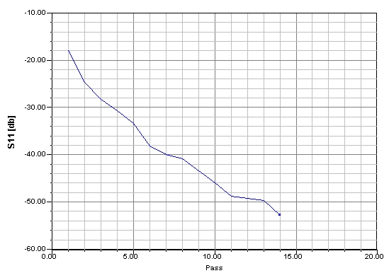
Using the Frequency Domain Solver, the initial results have been at -30 dB. If you force several adaptation passes, you can observe that the reflection drops from pass to pass. If the mesh is dense enough you also go bellow -60 dB (and lower). The S-Parameter change from pass to pass is acctualy below 1%. Maybe you should change the error creteria to an even lower number (0.1?)


F.
 

hfss gamma

1) For the sake of argument, below is a picture that shows dB(S11) as a function of the adaptive passes in HFSS on your model:
39_1158873296.jpg

I changed the waveport solution accuracy to 0.001% and added another convergce criteria on dB(S11). For better S11, just add more passes.

2) For more complex designs you should also consider Ansoft Designer. This will allow you to design building blocks in HFSS and link them together parameterically in the Ansoft Designer schematics together with the active components. Ansoft Designer dynamic link with HFSS allows you to interpolate existing HFSS solutions and will save you time (otherwise you would need much more parameteric simulations). For example, you can optimize or tune on the fly your passive circuits together the active devices.

3) Ansoft are now showing its annual seminars accross the world. Two of the presentations are in cooperation with Taiyo Yuden and UMS on 60 GHz designs. You might find it interesting. Browse to **broken link removed** for more details.

Regards,
Itai
 

hfss микрополосковая линия

Hi,

Thanks again, RFSimulator and Itai.

Due to your analysis, I think the main problem in my case is adaptive passes. Really appreciate for your helps!

For the last question:) To make sure the TL is 50ohm in HFSS, I plot the Ports Impedance in magnitude. Is that correct?
I asked it because I can see ripples in my S11, that should caused by imperfect matching, isn't it?

Best regards,
K
 

microstrip line hfss sinmulation

Hi itaifrenkel,

nice graph. As you see in my previous post I get about the same behaivior in the CST FD Solver. Can you tell us how many TETs are required for the last pass. Would be interesting to know if it is practical to run a larger design with an accuracy demand of -50 dB... (Question of course always is if you can measure accurately down to - 50 dB ;-) .

Thx.

F.
 

Status
Not open for further replies.

Part and Inventory Search

Welcome to EDABoard.com

Sponsor

Back
Top