Welcome to our site! EDAboard.com is an international Electronics Discussion Forum focused on EDA software, circuits, schematics, books, theory, papers, asic, pld, 8051, DSP, Network, RF, Analog Design, PCB, Service Manuals... and a whole lot more! To participate you need to register. Registration is free. Click here to register now.
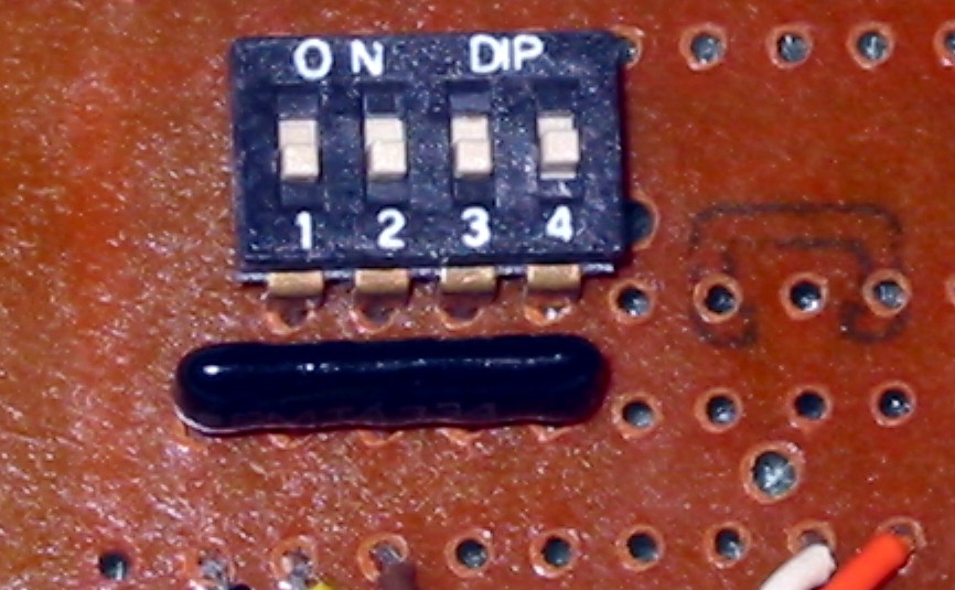
That thing below the DIP switch is 4-way pullup resistor network, something like 4x4.7kΩ or 4x10kΩ .. see picture below ..
It ensures that the input is held "H" if switch is open ..
One pin is the common that goes to Vcc and the other four pins are the free ends of the four resistors. The DIP switch connects the free ends to ground for a logic zero and leaves them floating for a logic one.
This site uses cookies to help personalise content, tailor your experience and to keep you logged in if you register.
By continuing to use this site, you are consenting to our use of cookies.