Continue to Site

Probing and scoping MegOhm circuits?

cupoftea

Advanced Member level 6
Joined
Jun 13, 2021
Messages
3,335
Helped
65
Reputation
132
Reaction score
154
Trophy points
63
Activity points
17,240
Hi,
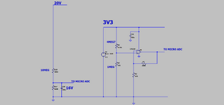
We have circuits with multiple MegOhm resistors in them. Rails are mostly 3V3 and 5V.
Resistors are as high as 22MEGs in places.

If probing the attached with say a scope probe, would you recommend a 100:1 probe?

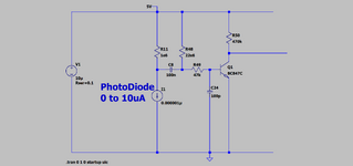
Also , please confirm that the "22MEG" circuit is useless?......i cant see any property of a photodiode that could ever help the collector of the NPN to ever go high?
Must admit that 22MEG resistor does look like an "elephant in the room" to me though?
(LTspice of "22MEG" circuit also attached)
 

Attachments

  • MEGOHM.png
    MEGOHM.png
    32.2 KB · Views: 54
  • 22MEG cct_.png
    22MEG cct_.png
    37.2 KB · Views: 48
  • 22meg cct.zip
    755 bytes · Views: 29
Last edited:
Thanks, i am not aware of too many 10Meg probes...the common ones i know of all have 1MEG shunt and 9 MEG series if 10:1, or 1MEG shunt and 99MEG series if 100:1?
Many 10 Mohm probes available on the market:

In earlier years, most 10:1 probes had 10 Mohm input R, increased bandwidth of modern passive probes often resulted in 1 Mohm.

Base node has 200 nA bias, 1 Mohm probe turns transistor off.
 
Voltage follower with opamp can be adequate active probe for this circuit. If you want, you can build the probe with high speed opamp, and low bias current (CMOS) for future use, but this circuit doesn’t need it.

I have been using 100M-1Gohm resistors in transimpedance amplifiers, 22MOhm doesn't look like an "elephant in the room"
 
I have been using 100M-1Gohm resistors in transimpedance amplifiers, 22MOhm doesn't look like an "elephant in the room"
Thanks yes, though i believe there are noise issues (as well as what FvM kindly points out) with around 22MEG and above.

...When you consider that in SMPS feedback loops, its pretty well taken as a golden rule that you need to keep upwards of 100uA in your output divider resistors otherwise your feedback signal is in danger of being drowned in noise. Obviously this applies especially to SMPS with transconductance error amplifiers where its the actual ratio of the output divider resistors which counts, rather than the value. This applies even to low power , low voltage DCDCs which when well layed out, dont spew loads of noise over these resistors.

I also remember some Guys from Japan coming over to buy a product from us....and them going nuts because they said they had seen a thumb print on a 10 MEG resistor. As you know, such impurity on a 10MEG can dramatically alter its effective value....(the resistance value "seen" between its pads.)

I would hate to think of a 22MEG with some dampness over it or dust coating......even if it had been coated over with conformal coating.

The cheapness of many standard electronics products doesnt allow for the extra manufacturing details which are needed for sucessful use of multi MEGOhm circuits.
 
Last edited:
Whenever I see a discrepancy, I always wonder, what are the differences in assumptions.

I never hesitated to use 33 Meg resistors for low f CMOS logic gates in my late '70's Aerospace days. For environmental protection, I added Silicone spray or more harsh environments like atmosphere reentry... GE RTV which even prevents exposed wires from getting melted or for RF ... tin-plated shields. They do make bigger resistors and Omega meters

"If probing the attached with say a scope probe, would you recommend a 100:1 probe?"
-
Only if desperate. I'd only probe the lower impedance points to imply the performance, which is what I was thinking, by measuring the Vbe instead. But, I was lucky to have Tek FET probes where ever I worked, which requires critical care of any voltages or ESD E-fields> 25V.

Frank you are correct! Your simulation proves 2uA is insufficient with a 1:1 scope probe on the 22 Meg resistor.

So I examined our differences in assumptions to understand the disparity in simulations,

1. Was it differences saturation current, Is for the transistor? I used 100 fA, The BC547A in LTspice is 4.679 E-14, possibly
2. Was it hFE which drops rapidly with Ic < 5 uA and has a wide tolerance? Possibly, I used hFE =50 ( spec is 90 nom. at 10uA)
3. Was it the input pulse freq.? LTspice used 100 Hz, I used > 5kHz , Yes it makes a difference to the transistor .
4. Was it the probe test point? Yes, I assumed Vbe as the critical test point, as the 47k 100 pF + probe attenuates the ripple and Rbe is a lower impedance at 2.6 uA

1743258448996.png
 
Last edited:
Thanks yes, though i believe there are noise issues (as well as what FvM kindly points out) with around 22MEG and above.
Don't know application of this circuit, but it can detect pulses <300nA all circuits with this sensitivity are sensitive to external noise.
Someone can make 300nA circuit with <1Mohm resistors. Sensitivity to leakage and mains hum will be similar.
I also remember some Guys from Japan coming over to buy a product from us....and them going nuts because they said they had seen a thumb print on a 10 MEG resistor. As you know, such impurity on a 10MEG can dramatically alter its effective value....(the resistance value "seen" between its pads.)
It is good practice to keep it clean. Did anyone measured this dramatic change? I can touch 100Mohm (1206) and there is no dramatic change.
I would hate to think of a 22MEG with some dampness over it or dust coating......even if it had been coated over with conformal coating.
It depends on voltage. Guard rings on PCB can nullify voltage and surface leakage.
 
Going back to the 22MEG photo diode circuit if i may....
...Thanks it all makes sense now.
As you discuss kindly, the circuit "works" when there is a *change* of light level on the photo diode.
The actual useage of this circuit is in a home for the blind, where the blind
traverse the corridors by sliding their hand along the hand rails on the walls.....if 2 blind people are there they can knock in to
each other. As such, these photo diode circuits are used in light block cct, where a human passing will block the led
light onto the photo detector, and then a pulse will be sent and an audible alarm goes off, warning the blind
walkers that another person is coming. I have actually now been terminated from this job as they suggested that I had posted to a forum!. This amazes me because
I have seen this circuit now literally all over the internet , so why they think its their personal secret is
beyond me. And besides, if another home for the blind benefits , then good-o, since these people
need all the help they can get. It most probably wows all that a common emitter BJT circuit is now considered a "top secret" design!
 
> this circuit is the derivative sensitivity is so high compared to the proportional, .... (unless that was the intent of this cct) ... was my initial comment.

What makes this design special isn’t the common transistor setup. It’s the way it uses a weak steady current (from a 22M resistor) and a much stronger decay current (22 times stronger, from a 1M resistor). This makes it ignore slow changes in light (like ambient light shifting) and only react to sudden drops in light (like something blocking the path).

Compared to the industry-standard infrared receivers made by Sharp and later Vishay, this design doesn’t offer any technical or cost benefits.

So, it doesn’t have much value as intellectual property.
 
Last edited:


Write your reply...

LaTeX Commands Quick-Menu:

Part and Inventory Search

Welcome to EDABoard.com

Sponsor

Back
Top