Eugen_E
Full Member level 6

Hello, I need help with a circuit I saw recently.
In radioamateur transceivers, like ICOM or Xiegu, etc. a "multifunction microphone" with keypad is used for push to talk (PTT), voice and remote commands to be sent to the transceiver. This multifunction microphone has to have proper EMI performance, so powerful RF signals don't affect it, and also key presses won't influence the sensitive receiver... so capacitor and inductor filters are used at both ends and also transient suppressors.
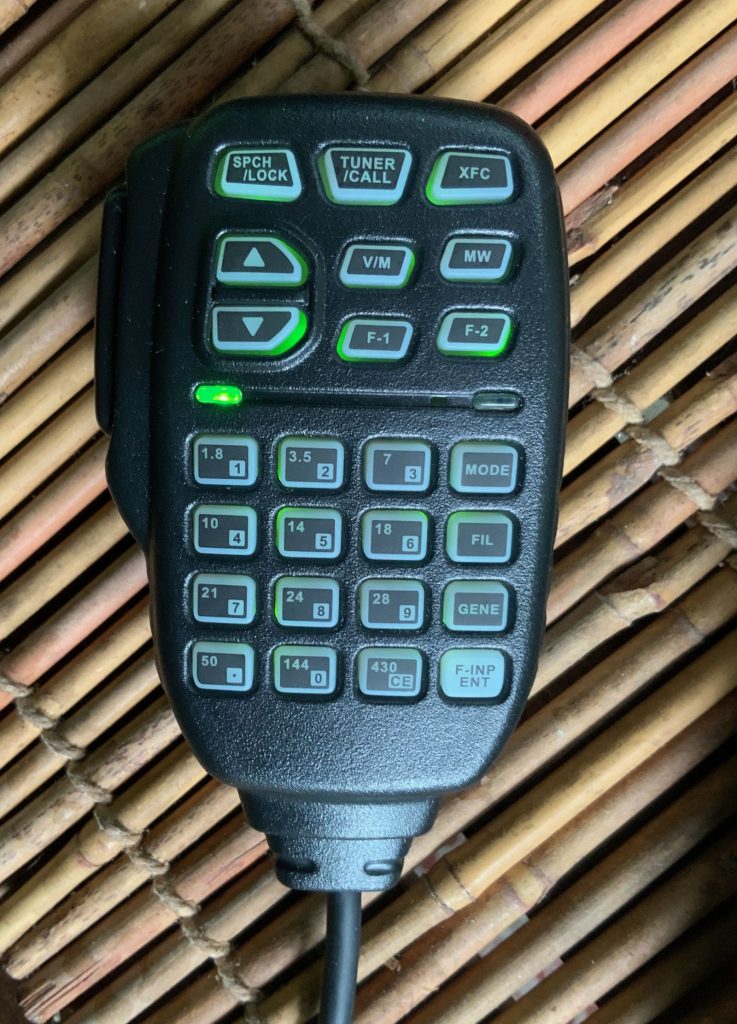
This microphone is connected with a 8 wire cable ~ 1 meter in length, similar to Ethernet cable, with modular connectors. Power and ground, audio from microphone on 2 wires to avoid ground loops, PTT, etc. signals are sent, and also a data signal for commands generated when pressing keys.
Here is a portion of the "multifunction microphone" circuit schematic,

and the transceiver circuit it connects to (from a Xiegu G90 transceiver):

MIC_DATA is a data signal (serial) generated by a microcontroller inside the "multifunction microphone", and sent through that strange circuit in red.
In the tranceiver, a comparator (in red) is used to recover the MDATA signal.
Questions:
- Why is that circuit with high value resistors used, instead of driving it directly with the microcontroler pin or some driver circuit designed for the cable impedance?
- The circuit for data transmission is sensitive to the capacitance of the cable used? And perfectly only with the OEM cable?
It works perfectly only during RX with CAT-5, CAT-5E, CAT-6 cable, if the pairs are crimped according to TIA/EIA568A and TIA/EIA568B.
But, when transmitting, RF is picked up by the MIC signals because the MIC signal wires are in different pairs... so a CAT7 or better, shielded cable is needed.
To avoid RF pickup, I tried to put the MIC wires in the same pair... but to my surprise, the data communication is not working anymore, maybe because it is expecting a specific cable capacitance...
Thanks
In radioamateur transceivers, like ICOM or Xiegu, etc. a "multifunction microphone" with keypad is used for push to talk (PTT), voice and remote commands to be sent to the transceiver. This multifunction microphone has to have proper EMI performance, so powerful RF signals don't affect it, and also key presses won't influence the sensitive receiver... so capacitor and inductor filters are used at both ends and also transient suppressors.
This microphone is connected with a 8 wire cable ~ 1 meter in length, similar to Ethernet cable, with modular connectors. Power and ground, audio from microphone on 2 wires to avoid ground loops, PTT, etc. signals are sent, and also a data signal for commands generated when pressing keys.
Here is a portion of the "multifunction microphone" circuit schematic,
and the transceiver circuit it connects to (from a Xiegu G90 transceiver):
MIC_DATA is a data signal (serial) generated by a microcontroller inside the "multifunction microphone", and sent through that strange circuit in red.
In the tranceiver, a comparator (in red) is used to recover the MDATA signal.
Questions:
- Why is that circuit with high value resistors used, instead of driving it directly with the microcontroler pin or some driver circuit designed for the cable impedance?
- The circuit for data transmission is sensitive to the capacitance of the cable used? And perfectly only with the OEM cable?
It works perfectly only during RX with CAT-5, CAT-5E, CAT-6 cable, if the pairs are crimped according to TIA/EIA568A and TIA/EIA568B.
But, when transmitting, RF is picked up by the MIC signals because the MIC signal wires are in different pairs... so a CAT7 or better, shielded cable is needed.
To avoid RF pickup, I tried to put the MIC wires in the same pair... but to my surprise, the data communication is not working anymore, maybe because it is expecting a specific cable capacitance...
Thanks
Last edited:
