ET1990
Newbie

- Joined
- Feb 16, 2024
- Messages
- 2
- Helped
- 0
- Reputation
- 0
- Reaction score
- 0
- Trophy points
- 1
- Activity points
- 34
Good evening to all,
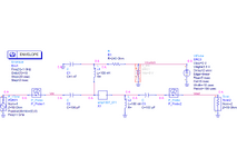
I just started to work with ADS, and so I am trying to reproduce a RF switch with PIN diode reported in this application note of the Infineon (pag. 12). This represents a real and working demo board. I took the parameter of the PIN diode from the SPICE model available at this URL and I copied them into the schematic.

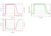
After the verification of the biasing with a “DC” simulation, I tried an “Envelope” simulation adopting a sinusoidal voltage source at the input of the switch and a step voltage source as control signal, but, as you can see, the behavior is not the expected one (there is no switching).

I saw the same result also with the "Transient" simulation. On the other hand, I saw that substituting the inductors and capacitors with their ideal counterparts “DC feed” and “DC block”, respectively, the result of the “Envelope” simulation is the expected one (even if the isolation is poor).

However, the "Transient" simulation shows again no switching. I made a lot of trials but I am not able to get the expected results with the complete circuit. Any suggestion? Thank a lot
I just started to work with ADS, and so I am trying to reproduce a RF switch with PIN diode reported in this application note of the Infineon (pag. 12). This represents a real and working demo board. I took the parameter of the PIN diode from the SPICE model available at this URL and I copied them into the schematic.
After the verification of the biasing with a “DC” simulation, I tried an “Envelope” simulation adopting a sinusoidal voltage source at the input of the switch and a step voltage source as control signal, but, as you can see, the behavior is not the expected one (there is no switching).
I saw the same result also with the "Transient" simulation. On the other hand, I saw that substituting the inductors and capacitors with their ideal counterparts “DC feed” and “DC block”, respectively, the result of the “Envelope” simulation is the expected one (even if the isolation is poor).
However, the "Transient" simulation shows again no switching. I made a lot of trials but I am not able to get the expected results with the complete circuit. Any suggestion? Thank a lot


