Bobson2000
Junior Member level 2

Hi.
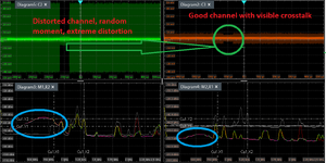
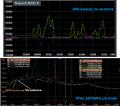
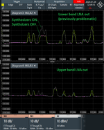
Im launching radio receiver for two bands. First RF path is common and containst two LNAs, next the path is splitted to two channels. Each channel starts with pass-band filter, and LNA TRF37D73 after him. First channel/band with center freq 1575MHz works well, i have about 8mVpp on LNA (U21) out , when antenna input is floating/matched. But on second channel/band with center frequency 1232MHz have some problem - on LNA (U18) output i get floor about 20mVpp, with unexpected jumps to 25, 30, 40mVpp (one time i got about 240mVpp). Jumps are unexpectable time, form couple microseconds, to couple of miliseconds. This signal level causes ADC overload on end of path. With eliminating method i come to conclusion that problem source is U18 LNA.
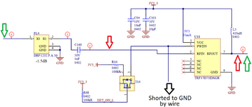
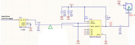
On LNA's outputs circut was the same schematics - has just matching bias coil - series capacitor - UFL connector when im measuring. PCB layout is in some part different. TRF37D73 is unconditionable stable LNA.
1. Probably most significant test i have don was: crossing channels on LNAs (U18,U21) inputs (on C160,C130) - distortion still occurs in the same channel which contain U18 - so i think everything before LNA's can be eliminated from suspects, including pasband filters. Second channel looks proper, have just some crosstalk form distorted channel
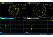
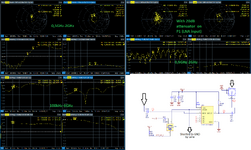
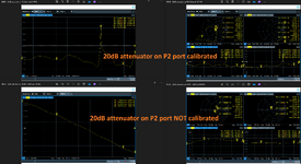
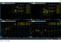
2. I measured LNA in PCB, by VNA for full VNA band 100k-6GHz. Gain looks property, S11 max value is about -3dB (so it should be stable), in interesting band is about -18dB. S11, S22 impedances
looks proper, S22 is distorted but i used 20dB attenuator on P2 port.
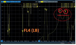
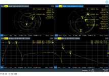
3. I measured stage with splitters and pasband filters by VNA, and for my band it looks proper (S11, S22 impedance). Filter has own in/out impedance matching. I do not measured it on full VNA frequency range, but i will do it further.
4. I tried too: changing LNA supply source, adding 10u, 1u, 100n capacitors to LNA supply, connecting supply direct from C101 to LNA on top layer (is not done on PCB layout as You can see), connecting supply by ferrite bead, adding resistor (10R) in series to biasing output coil, with 10p and 100n capacitors, changing this coil to producer suggestes 100nH, adding ~800R resistor shunt on LNA input, replacing LNA, filter, connecting directly LNA input to filter input, or splitter input/output (of course removing filter/splitter), "adding" vias to supply capacitors (by connecting it with vias stitching). I tried to place finger on supply decoupling capacitors, and distotrion not decerases, but incerases about 30%.
5. I readed some topics about LNA oscillating issues, and stability, i tried some suggested there solutions, but no find no working solution in my case, and now im near hit the wall . I tried all this solutions/changes, but i don't see significant or "going to better way" solutions.
6. Now im trying to get possible impedance mismatch caused by SAW pass-band filter on out band frequencies, because when i just short LNA input by 50R i get proper value on LNA out (in progress). Filter in first channel/band has external matching coil (as datasheet suggest), but in distorted channel/band i will probable need them too.
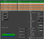
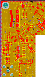
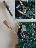
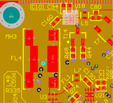
I added some graphics: piece of layout, schematic, and measured by VNA: LNA, splitter to filter stage (J1-FL4), measured distortions on LNA out. Did You have some sugestions, what should i try, or meas?
Best regards.
Im launching radio receiver for two bands. First RF path is common and containst two LNAs, next the path is splitted to two channels. Each channel starts with pass-band filter, and LNA TRF37D73 after him. First channel/band with center freq 1575MHz works well, i have about 8mVpp on LNA (U21) out , when antenna input is floating/matched. But on second channel/band with center frequency 1232MHz have some problem - on LNA (U18) output i get floor about 20mVpp, with unexpected jumps to 25, 30, 40mVpp (one time i got about 240mVpp). Jumps are unexpectable time, form couple microseconds, to couple of miliseconds. This signal level causes ADC overload on end of path. With eliminating method i come to conclusion that problem source is U18 LNA.
On LNA's outputs circut was the same schematics - has just matching bias coil - series capacitor - UFL connector when im measuring. PCB layout is in some part different. TRF37D73 is unconditionable stable LNA.
1. Probably most significant test i have don was: crossing channels on LNAs (U18,U21) inputs (on C160,C130) - distortion still occurs in the same channel which contain U18 - so i think everything before LNA's can be eliminated from suspects, including pasband filters. Second channel looks proper, have just some crosstalk form distorted channel
2. I measured LNA in PCB, by VNA for full VNA band 100k-6GHz. Gain looks property, S11 max value is about -3dB (so it should be stable), in interesting band is about -18dB. S11, S22 impedances
looks proper, S22 is distorted but i used 20dB attenuator on P2 port.
3. I measured stage with splitters and pasband filters by VNA, and for my band it looks proper (S11, S22 impedance). Filter has own in/out impedance matching. I do not measured it on full VNA frequency range, but i will do it further.
4. I tried too: changing LNA supply source, adding 10u, 1u, 100n capacitors to LNA supply, connecting supply direct from C101 to LNA on top layer (is not done on PCB layout as You can see), connecting supply by ferrite bead, adding resistor (10R) in series to biasing output coil, with 10p and 100n capacitors, changing this coil to producer suggestes 100nH, adding ~800R resistor shunt on LNA input, replacing LNA, filter, connecting directly LNA input to filter input, or splitter input/output (of course removing filter/splitter), "adding" vias to supply capacitors (by connecting it with vias stitching). I tried to place finger on supply decoupling capacitors, and distotrion not decerases, but incerases about 30%.
5. I readed some topics about LNA oscillating issues, and stability, i tried some suggested there solutions, but no find no working solution in my case, and now im near hit the wall
6. Now im trying to get possible impedance mismatch caused by SAW pass-band filter on out band frequencies, because when i just short LNA input by 50R i get proper value on LNA out (in progress). Filter in first channel/band has external matching coil (as datasheet suggest), but in distorted channel/band i will probable need them too.
I added some graphics: piece of layout, schematic, and measured by VNA: LNA, splitter to filter stage (J1-FL4), measured distortions on LNA out. Did You have some sugestions, what should i try, or meas?
Best regards.
Attachments
-
 U18 sch.png180.1 KB · Views: 127
 -
 U18 input - J4 output, 0,1-6GHz, cal 20dB att on P2 (soldered SMA cable) (1).PNG78.2 KB · Views: 139
 -
 J1-FL4 out, without C160 (measured by soldered SMA cable)(2).PNG76.2 KB · Views: 116
 -
 U18 pcb.png429.3 KB · Views: 167
 -
 U18 LNA out distortions.png2.1 MB · Views: 148
Last edited:

