Continue to Site

Welcome to EDAboard.com

Welcome to our site! EDAboard.com is an international Electronics Discussion Forum focused on EDA software, circuits, schematics, books, theory, papers, asic, pld, 8051, DSP, Network, RF, Analog Design, PCB, Service Manuals... and a whole lot more! To participate you need to register. Registration is free. Click here to register now.

Buck converter design help needed

Status
Not open for further replies.

sneed

Newbie level 4
Newbie level 4
Joined
Feb 11, 2023
Messages
6
Helped
0
Reputation
0
Reaction score
0
Trophy points
1
Activity points
161
Hello,
I am a mechanical engineering student and I am working on a relay controller. My logic circuits all operate on 5v, but my only available power source is 24v. My entire circuit will draw around 250mA normally, with millisecond peaks at 300mA every 10 minutes (relay switching).

I need help designing a buck controller to step the voltage down. It is crucial for my application that I get the maximum efficiency possible- minimizing heat generation. I will have temperature sensors in close proximity to the converter and the logic and I want to avoid "tainting" the data they collect to the best of my ability.

First I checked what is available on the market. Converter ICs based around MP2307 MP1584 LM2596 etc.
"protosupplies.com"
This website has tables under all their product listings showing measured temperature and efficiency values. At first I was surprised to see cheaper ICs using less efficient chips were actually running cooler. But then I quickly realized that the reason was the larger higher quality inductors used on their ICs. Small and cheap components (as well as low surface area) make for more heat generation.

I've done a lot of reading on buck converters, linear regulators, and all of their components and inner workings, as well as the mathematical relations in choosing their parts- in an attempt to design my own. However, I read that components such as inductors and capacitors need to be oversized to compensate for manufacturers overmarketing them with inflated specs. I do not know how to oversize electrical components. The same way I know how to oversize an axle or a shaft; where I know how much larger it needs to be to be stronger- but still play nice with all the other components, I am not that fluent in the realm of electrical engineering. I've played around with multiple parts spec calculators on reputable vendor sites in an attempt to get somewhere.
I feel lost and I am here to ask for the help of someone well versed in this topic, with practical real life experience in the field, who can advise me on how to choose my parts.

Important points:
24v to 5v
250-300mA draw on the 5v side
Cost and size are irrelevant- need the best performance possible
Minimum heat generation
Best chip? inductor spec? capacitor spec? *for my application
any input helps
Currently am leaning towards this chip: MP2315S. Is there a better one?

If you would be so kind as to offer advice or even recommendations, please explain your reasoning so that I can learn.
Thanks a million :)

*I could not find any rule against it so I am sorry if this is against the rules but I am willing to pay for your expertise. If this is against the rules please let me know I will edit it out*
 
Last edited:

The MP2315S looks to have a maximum input of 24VDC so if your looking at operating at 24VDC i'd suggest a device with some headroom, maybe the MP2338 https://www.monolithicpower.com/en/products/mp2338.html. To step down at this current an inductor such as https://www.we-online.com/en/components/products/datasheet/744065560.pdf will be needed, this has a operating current of 1.25A and doesn't start saturating until 1.1A which gives you plenty of headroom from your maximum current.

A 10uF output capacitor such as https://uk.farnell.com/tdk/c1608x5r1a106k080ac/cap-10-f-10v-10-x5r-0603/dp/2211164?st=10uf 10v should suffice.

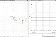
Attached is a crude simulation.

Assumed a 20-28VDC input range (because you need some allowance for power rail variation) and assume 5V 2W Output (to give some margin on you max stated output)
450khz operating frequency (fixed by the IC)
 

Attachments

  • Sch.jpg
    Sch.jpg
    321.8 KB · Views: 217
Last edited:
  • Like
Reactions: sneed

    sneed

    Points: 2
    extremely helpful, went above and beyond to help me pick parts for a project, explained why they picked those parts as well so that I could understand
Hi,

Good job so far.

Regarding "oversizing". I'm doing advanced electronics design for decades now. I use big brand parts and can say you can trust the datasheet.
But one needs to carefully read them. Different brand have different test conditions thus they may get different results. So don't just compare a single value, but also the test conditions.

Heat and efficiency, physics: Two converters with equal efficiency will generate the same power of heat (dissipated power), but still may generate different temperatures. This may be because of different size, air flow, heat spreading. You may use (active) cooling, water cooling, peltier, fans, heatsinks ... and so on to improve on this. But the PCB layout will play a big role. Physical distance, heat spreading techniques (copper layers, vias), placing the parts on opposite side of the PCB, blocking the heat by milled slots ... will also improve the situation.

But with one requirement I have my problems: "best performance possible".
I don't do designs with this requirement unless the customer gives me endless time and money.
Without a true specification there is no end. A true specification needs a limit with value and unit, as well as a definition on how to measure the "performance".
Is it pure efficiency (power dissipation), the hottest spot temperature rise, the temperature error at the sensor ... in an open circuit, a closed box, with fan.... what is the reference?

Back to the converters: what generates heat?
* every current carried by a ohmic resistance (coil winding, copper trace...)
* conduction loss in a switch (transistor)
* switching loss of the switching part
* core loss in the inductor
* diode loss.

Improvements:
The average output current is about 250mA. But for heat generation you need to calculate with RMS currents. These depend on switching duty cycle. So if possible (physical limits) use high duty cycle. Use low resistance coils and short traces (thick, wide).
Conduction loss also depends on duty cycle, but also on R_ds_ON. The swithes' ON resistance.
Switching loss depends a lot on drive current, stray capacitance, stray inductance, switching frequency, switching time...
Lower switching frequency, but steep edges are good, but may cause HF interferance problems.
Core loss depends on core material and switching timing / frequency. Use HF core material.
Diode loss depends on duty cycle, switching timing and forward voltage. Try to use "synchronous buck", they use a driven Mosfet as a diode with much lower voltage drop.

Klaus
 
  • Like
Reactions: sneed

    sneed

    Points: 2
    very insightful, raised a lot of good points, educational and informative
The MP2315S looks to have a maximum input of 24VDC so if your looking at operating at 24VDC i'd suggest a device with some headroom, maybe the MP2338 https://www.monolithicpower.com/en/products/mp2338.html. To step down at this current an inductor such as https://www.we-online.com/en/components/products/datasheet/744065560.pdf will be needed, this has a operating current of 1.25A and doesn't start saturating until 1.1A which gives you plenty of headroom from your maximum current.

A 10uF output capacitor such as https://uk.farnell.com/tdk/c1608x5r1a106k080ac/cap-10-f-10v-10-x5r-0603/dp/2211164?st=10uf 10v should suffice.

Attached is a crude simulation.

Assumed a 20-28VDC input range (because you need some allowance for power rail variation) and assume 5V 2W Output (to give some margin on you max stated output)
450khz operating frequency (fixed by the IC)
I greatly appreciate you taking the time to find and recommend parts. Thank you for addressing my oversight in the variation of input voltage. The simulation is above and beyond. Many thanks.
--- Updated ---

Hi,

Good job so far.

Regarding "oversizing". I'm doing advanced electronics design for decades now. I use big brand parts and can say you can trust the datasheet.
But one needs to carefully read them. Different brand have different test conditions thus they may get different results. So don't just compare a single value, but also the test conditions.

Heat and efficiency, physics: Two converters with equal efficiency will generate the same power of heat (dissipated power), but still may generate different temperatures. This may be because of different size, air flow, heat spreading. You may use (active) cooling, water cooling, peltier, fans, heatsinks ... and so on to improve on this. But the PCB layout will play a big role. Physical distance, heat spreading techniques (copper layers, vias), placing the parts on opposite side of the PCB, blocking the heat by milled slots ... will also improve the situation.

But with one requirement I have my problems: "best performance possible".
I don't do designs with this requirement unless the customer gives me endless time and money.
Without a true specification there is no end. A true specification needs a limit with value and unit, as well as a definition on how to measure the "performance".
Is it pure efficiency (power dissipation), the hottest spot temperature rise, the temperature error at the sensor ... in an open circuit, a closed box, with fan.... what is the reference?

Back to the converters: what generates heat?
* every current carried by a ohmic resistance (coil winding, copper trace...)
* conduction loss in a switch (transistor)
* switching loss of the switching part
* core loss in the inductor
* diode loss.

Improvements:
The average output current is about 250mA. But for heat generation you need to calculate with RMS currents. These depend on switching duty cycle. So if possible (physical limits) use high duty cycle. Use low resistance coils and short traces (thick, wide).
Conduction loss also depends on duty cycle, but also on R_ds_ON. The swithes' ON resistance.
Switching loss depends a lot on drive current, stray capacitance, stray inductance, switching frequency, switching time...
Lower switching frequency, but steep edges are good, but may cause HF interferance problems.
Core loss depends on core material and switching timing / frequency. Use HF core material.
Diode loss depends on duty cycle, switching timing and forward voltage. Try to use "synchronous buck", they use a driven Mosfet as a diode with much lower voltage drop.

Klaus
Hey Klaus,
I read your replies on many other posts and am glad you responded to mine. You make a very good point about test conditions, and their deciding effect on results. I will be using a milled peninsula to isolate my temp sensors and lower the thermal mass around them.
I know "best performance" is endless like you said. I would say my definition/specification would be highest efficiency. To me highest efficiency is synonymous with "lowest amount of heat output" aka lowest dissipated power- regardless of how well it dissipates heat or the highest temp spot on it, if it puts out as little heat as possible, it will affect my readings as little as possible. Everything else is secondary, though surely related. (EX. lower resistance wire is thicker and also dissipates heat better due to larger surface area)

The cost of available devices and the prices of components I have seen, combined with this being only one unit production, have led me to be curious about how much it can end up costing. If I were to mass produce, I would surely optimize the cost to the performance, and pick where I want to be on the curve of diminishing returns. But on this post I just wanted to see how crazy it can get. The other half of the what you mention is time. I am grateful to you and scope for taking the time to respond to me and offer your expertise.

To give you a little bit of context, the FINAL system will be in a box ~7.5cm tall ~11cm wide ~2cm deep. All four of the 2cm "depth" sides will be perforated in a way to allow thermal conduction of the air, but not for fast air velocity (same design as the grille on bulletproof vehicles to let air through to radiator but not bullets). Essentially, those sensors are there to measure properties of mostly stagnant ambient air. The prototype I am working on has no size constraint but will be in a similarly designed box with the vented sides.

Response to "improvements" section:
I read that synchronous is the way to go, but there is a point (at low current?) where they are inefficient.
You infer duty cycle and size? are related? I thought duty cycle just meant the ratio between input and output voltage. The ratio of time the high and low side switches are open.
I vaguely remember that a lower frequency is related to better efficiency with a tradeoff of the components being larger?
I know a lot of these converters are used in radios and people worry about noise and inductance. I am not concerned about it as I have no other inductors or RF components in use.

Conclusions drawn so far:
The inductance decides the ripple current... but I also want low resistance in the inductor. And an HF core.
Ceramic capacitors have better properties than electrolytic for this application.
Synchronous buck is the choice for me.
I don't need to oversize if I buy from a reputable manufacturer, just have to pay attention to testing conditions.
Wide traces.
--- Updated ---

The MP2315S looks to have a maximum input of 24VDC so if your looking at operating at 24VDC i'd suggest a device with some headroom, maybe the MP2338 https://www.monolithicpower.com/en/products/mp2338.html. To step down at this current an inductor such as https://www.we-online.com/en/components/products/datasheet/744065560.pdf will be needed, this has a operating current of 1.25A and doesn't start saturating until 1.1A which gives you plenty of headroom from your maximum current.

A 10uF output capacitor such as https://uk.farnell.com/tdk/c1608x5r1a106k080ac/cap-10-f-10v-10-x5r-0603/dp/2211164?st=10uf 10v should suffice.

Attached is a crude simulation.

Assumed a 20-28VDC input range (because you need some allowance for power rail variation) and assume 5V 2W Output (to give some margin on you max stated output)
450khz operating frequency (fixed by the IC)
Could you explain your reasoning for choosing an inductance value of 56µH?
On the MP2338 datasheet they use a 6.8µH inductor to step down from 24v to 5v.
Also, it has an DCR of 16mΩ. The WE-TPC SMT Shielded Tiny Power Inductor has ~200mΩ.
 
Last edited:

I greatly appreciate you taking the time to find and recommend parts. Thank you for addressing my oversight in the variation of input voltage. The simulation is above and beyond. Many thanks.
--- Updated ---


Hey Klaus,
I read your replies on many other posts and am glad you responded to mine. You make a very good point about test conditions, and their deciding effect on results. I will be using a milled peninsula to isolate my temp sensors and lower the thermal mass around them.
I know "best performance" is endless like you said. I would say my definition/specification would be highest efficiency. To me highest efficiency is synonymous with "lowest amount of heat output" aka lowest dissipated power- regardless of how well it dissipates heat or the highest temp spot on it, if it puts out as little heat as possible, it will affect my readings as little as possible. Everything else is secondary, though surely related. (EX. lower resistance wire is thicker and also dissipates heat better due to larger surface area)

The cost of available devices and the prices of components I have seen, combined with this being only one unit production, have led me to be curious about how much it can end up costing. If I were to mass produce, I would surely optimize the cost to the performance, and pick where I want to be on the curve of diminishing returns. But on this post I just wanted to see how crazy it can get. The other half of the what you mention is time. I am grateful to you and scope for taking the time to respond to me and offer your expertise.

To give you a little bit of context, the FINAL system will be in a box ~7.5cm tall ~11cm wide ~2cm deep. All four of the 2cm "depth" sides will be perforated in a way to allow thermal conduction of the air, but not for fast air velocity (same design as the grille on bulletproof vehicles to let air through to radiator but not bullets). Essentially, those sensors are there to measure properties of mostly stagnant ambient air. The prototype I am working on has no size constraint but will be in a similarly designed box with the vented sides.

Response to "improvements" section:
I read that synchronous is the way to go, but there is a point (at low current?) where they are inefficient.
You infer duty cycle and size? are related? I thought duty cycle just meant the ratio between input and output voltage. The ratio of time the high and low side switches are open.
I vaguely remember that a lower frequency is related to better efficiency with a tradeoff of the components being larger?
I know a lot of these converters are used in radios and people worry about noise and inductance. I am not concerned about it as I have no other inductors or RF components in use.

Conclusions drawn so far:
The inductance decides the ripple current... but I also want low resistance in the inductor. And an HF core.
Ceramic capacitors have better properties than electrolytic for this application.
Synchronous buck is the choice for me.
I don't need to oversize if I buy from a reputable manufacturer, just have to pay attention to testing conditions.
Wide traces.
--- Updated ---


Could you explain your reasoning for choosing an inductance value of 56µH?
On the MP2338 datasheet they use a 6.8µH inductor to step down from 24v to 5v.
Also, it has an DCR of 16mΩ. The WE-TPC SMT Shielded Tiny Power Inductor has ~200mΩ
I recall they are targeting a 3A output (5V * 3A = 15W) so the current ripple they have calculated for would probably have being 40% of that, I rated my circuit for the 5V 2W (0.4A) which met your requirement. The lower current ripple as a percentage of the lower defined current load gives a larger inductance value but also likely a smaller physical device due to the reduced power.

The choke resistance is directly linked to the length of wire used to create the inductance within the choke. Higher inductance requires more turns and as such results in higher resistance. Resistance isn't always a bad thing as it often lowers the Q of the choke which is often desirable for EMI etc.. so its not a clear cut choice. The device i suggested is designed for switcher type applications.
 
Last edited:
  • Like
Reactions: sneed

    sneed

    Points: 2
    great explanation, easy to understand
Hi,

Without "power dissipation limit" I will ignore all the vague descriptions. In my opinion they are useless:
Lets say there is a solution with 100mW of dissipated power, then another member finds a solution that saves
10 mW (now 90 mW), next member saves additional 1mW (now 89mW), next saves another 10uW, 1uW, nanowatts, picowatts..
There is no end ... as long as you don't define one.

You say the load is 250mA ... 300mA @ 5V .... this already means your "load" dissipates
1250mW ... 1500mW with an uncertainty of 250mW.
How much sense does it make to focus on the step down while your "load" has the biggest influence on error at all?

Then you speak about "low current inefficiency".
The lowest current you gave are 250mA .... is there even less?
Let's say 100mA.
--> Then the value of 250mA is meaningless and you have to state: 100mA ... 300mA.

And while the efficiency at low current may drop ... you still can expect lower dissipated power:
300mA@5V and 90% efficiency gives 150mW of dissipated power.
200mA@5V and 88% efficiency gives 120mW of dissipated power.
And it all ends at Ptot= input_voltage × no_load_input_current

Duty cycle:
Indeed it depends on input voltage and output voltage.
But also on
* CCM vs DCM of switch mode operation
* burst mode vs continous switching
* and in detail on fixed vs variable frequency
* maybe others.

Generated heat:
If all conditions are constant (which surely can't be guaranteed with temperature measurements)
constant heat will cause constant temperature rise. And thus it can be calibrated.
Thus a way to improve overall performance could be to keep the output current constant.
Like: if the max current is 300mA ... you get 1500mW of power dissipation in the application circuit (your load).
Now if your application current drops to 250mA you could "dissipate" the difference of 50mA x 5V to get constant power dissipation ... and constant efficiency in the step down.
This does not improve accuracy, but it will improve precision.

But if we talk about accuracy:
You surely know that any (sun) light will cause errors, the color of your case, any external air flow, mounting method, even a person near the sensor will cause noticable errors due to the temperature radiation over a relatively high area (skin).
Birds, insects, spider webs ....

I can only recommend to give any hint on what "accuracy" and "precision" you target for.
Vague text will be meaningless. --> Use numbers.

Klaus
 
  • Like
Reactions: sneed

    sneed

    Points: 2
    In depth explanation, clear demonstration of expertise Thank you
I recall they are targeting a 3A output (5V * 3A = 15W) so the current ripple they have calculated for would probably have being 40% of that, I rated my circuit for the 5V 2W (0.4A) which met your requirement. The lower current ripple as a percentage of the lower defined current load gives a larger inductance value but also likely a smaller physical device due to the reduced power.

The choke resistance is directly linked to the length of wire used to create the inductance within the choke. Higher inductance requires more turns and as such results in higher resistance. Resistance isn't always a bad thing as it often lowers the Q of the choke which is often desirable for EMI etc.. so its not a clear cut choice. The device i suggested is designed for switcher type applications.
Thank you for the concise and detailed explanation regarding the power ripple, and explaining the coils and resistance, and how they apply to my use case. I understand now.
--- Updated ---

Hi,

Without "power dissipation limit" I will ignore all the vague descriptions. In my opinion they are useless:
Lets say there is a solution with 100mW of dissipated power, then another member finds a solution that saves
10 mW (now 90 mW), next member saves additional 1mW (now 89mW), next saves another 10uW, 1uW, nanowatts, picowatts..
There is no end ... as long as you don't define one.

You say the load is 250mA ... 300mA @ 5V .... this already means your "load" dissipates
1250mW ... 1500mW with an uncertainty of 250mW.
How much sense does it make to focus on the step down while your "load" has the biggest influence on error at all?

Then you speak about "low current inefficiency".
The lowest current you gave are 250mA .... is there even less?
Let's say 100mA.
--> Then the value of 250mA is meaningless and you have to state: 100mA ... 300mA.

And while the efficiency at low current may drop ... you still can expect lower dissipated power:
300mA@5V and 90% efficiency gives 150mW of dissipated power.
200mA@5V and 88% efficiency gives 120mW of dissipated power.
And it all ends at Ptot= input_voltage × no_load_input_current

Duty cycle:
Indeed it depends on input voltage and output voltage.
But also on
* CCM vs DCM of switch mode operation
* burst mode vs continous switching
* and in detail on fixed vs variable frequency
* maybe others.

Generated heat:
If all conditions are constant (which surely can't be guaranteed with temperature measurements)
constant heat will cause constant temperature rise. And thus it can be calibrated.
Thus a way to improve overall performance could be to keep the output current constant.
Like: if the max current is 300mA ... you get 1500mW of power dissipation in the application circuit (your load).
Now if your application current drops to 250mA you could "dissipate" the difference of 50mA x 5V to get constant power dissipation ... and constant efficiency in the step down.
This does not improve accuracy, but it will improve precision.

But if we talk about accuracy:
You surely know that any (sun) light will cause errors, the color of your case, any external air flow, mounting method, even a person near the sensor will cause noticable errors due to the temperature radiation over a relatively high area (skin).
Birds, insects, spider webs ....

I can only recommend to give any hint on what "accuracy" and "precision" you target for.
Vague text will be meaningless. --> Use numbers.

Klaus
I completely get what you are saying. The concept of my numbers being the biggest source of error is something I definitely see.
I also like the point you bring up about calibrating my sensors to account for the heat as it will be virtually constant.
I appreciate your time as well as the real life examples you used to back your points.

To clarify, the "low current inefficiency" I mentioned was simply about quantitatively low currents (less than X amount, of which I was unsure) but your reply leads me to believe it is a relative value to what the device has been designed for instead. I was not aware.

To add to your points about real life factors such as critters and sunlight, PCB design and a million other things can also affect the real life performance of a theoretically specced part- it may be the same, but often times it will vary. The final step is always to test and tune.
I will take what you guys have provided me with, apply it, and then measure measure measure.

All in all, you and scopeprobe gave me a great starting place, lots of practical knowledge, as well as awareness of factors I had not considered. This forum is a great resource and I am very grateful for your time and help. Hopefully this post serves as a resource for at least one other person looking for answers to a question similar to mine.

Thank you I am grateful :)
 
Last edited:

Hello,
I am a mechanical engineering student and I am working on a relay controller. My logic circuits all operate on 5v, but my only available power source is 24v. My entire circuit will draw around 250mA normally, with millisecond peaks at 300mA every 10 minutes (relay switching).

I need help designing a buck controller to step the voltage down. It is crucial for my application that I get the maximum efficiency possible- minimizing heat generation. I will have temperature sensors in close proximity to the converter and the logic and I want to avoid "tainting" the data they collect to the best of my ability.

First I checked what is available on the market. Converter ICs based around MP2307 MP1584 LM2596 etc.
"protosupplies.com"
This website has tables under all their product listings showing measured temperature and efficiency values. At first I was surprised to see cheaper ICs using less efficient chips were actually running cooler. But then I quickly realized that the reason was the larger higher quality inductors used on their ICs. Small and cheap components (as well as low surface area) make for more heat generation.

I've done a lot of reading on buck converters, linear regulators, and all of their components and inner workings, as well as the mathematical relations in choosing their parts- in an attempt to design my own. However, I read that components such as inductors and capacitors need to be oversized to compensate for manufacturers overmarketing them with inflated specs. I do not know how to oversize electrical components. The same way I know how to oversize an axle or a shaft; where I know how much larger it needs to be to be stronger- but still play nice with all the other components, I am not that fluent in the realm of electrical engineering. I've played around with multiple parts spec calculators on reputable vendor sites in an attempt to get somewhere.
I feel lost and I am here to ask for the help of someone well versed in this topic, with practical real life experience in the field, who can advise me on how to choose my parts.

Important points:
24v to 5v
250-300mA draw on the 5v side
Cost and size are irrelevant- need the best performance possible
Minimum heat generation
Best chip? inductor spec? capacitor spec? *for my application
any input helps
Currently am leaning towards this chip: MP2315S. Is there a better one?

If you would be so kind as to offer advice or even recommendations, please explain your reasoning so that I can learn.
Thanks a million :)

*I could not find any rule against it so I am sorry if this is against the rules but I am willing to pay for your expertise. If this is against the rules please let me know I will edit it out*
You can get such converters for about a buck or 2. They'e available everywhere. Such huge analysis seems an overkill imho.

Here's a few :
model 1
model 2
model 3
etc
 
Hi,
All in all, you and scopeprobe gave me a great starting place,
It started with one of the best first posts I've read here in this forum.
We got a lot of important informations: your state of knowledge, technical informations, targets, and what you did so far.
And you are not upset when I ask twice for informations that I personally find rather important.
This encourages me to help.

Klaus
 
You can get such converters for about a buck or 2. They'e available everywhere. Such huge analysis seems an overkill imho.

Here's a few :
model 1
model 2
model 3
etc
I agree it can be considered overkill. I prefer to call it optimization haha. Seeing videos of mass produced units being tested left me disappointed. After all, if a device is made to output 3A at 5v that is several times more than .5A at 5v. We can see that with the inductance values changing nearly tenfold for my current. For my application, every watt counts, and this is a learning opportunity. I am going to buy a few off the shelf units, and make a few of my own. I will test them and post the results. Thermal images and all. By the end we will know if it is or isn't overkill.

side note
I took an introductory circuits course a while back and have been dabbling in RF (I have helium miners on a few of the tallest buildings on the east coast of the US). Electronics design and repair have always interested me, but seemed daunting. Thanks to this topic though, I have gained the motivation to learn and to save up for an oscilloscope, artificial load, and power supply.
 

If you wish to experiment then this 2-transistor buck converter could be interesting.
Components are arranged so the inductor provides a sense signal. The converter is self-oscillating. Adjust the potentiometers to obtain desired performance.

The principle is similar to a design at this link:


buck converter 2-transistor 24v supply output 5VDC 250mA.png
 
I am going to chip away at this project and post my progress here. I am currently on my hardest semester (numerical differential equations) and also this is the last semester of my two semester project, which I need to complete to get my degree. It is a group project, in which I am the only member doing any work. But I'll spare you the tears haha. All in all, I am very busy, but I will continue to push through post my work.
I have familiarized myself with PCB designing software, and began to design my own PCB on paper (image included at the end of this text body). I know about the "no 90 degree turn" thing and my drawing is very crude (doesn't account for trace width or component size), but it is just to help me visualize general locations, orientations, and trace paths. I made everything one layer but I am likely going to do two layers on the software designer where applicable to get everything as close as possible with nice wide traces.
The hand drawing is a general layout for the MP2328 and MP2338. They both have 8 legs and use very similar components.
MP23X8.jpg

I will be attempting to make PCBs for the following:
-MP2328 using MP recommended components (diagram included)
MP2328.jpg

-MP2338 using MP recommended components (diagram included)
MP2338.jpg

-MP2338 using scopeprobe recommended components-->
For scopeprobe's, I have been attempting to do the math on the resistors and capacitors for the rest of the circuit. There are 14 formulae on the datasheet:
"https://www.monolithicpower.com/en/...sheet/lang/en/sku/MP2338GTL/document_id/9461/"
Around 12 apply. (there is one for POSCAP resistor and one for ceramic resistor, I will be using ceramic, etc.)
Haven't gotten very far. MP wants the consumer to use their components and the supplied data is pretty weak imho. That and I am not an electrical engineer, so maybe I am missing something super obvious.
I have included my notes. Everything relevant has the corresponding formula # from the datasheet by it. (I am 100% certain my scribbles are 100% useless but I am just showing that I tried)
IMG_4993.jpg
IMG_4994.jpg
IMG_4995.jpg

I have also been considering the MP2317 using MP recommended components (diagram included)
MP2317.jpg

I like the MP2317 because it is simpler with 6 legs. Appeases the minimalist in me. However the switching frequency is 600kHz, 150 more than the others. This is bad for efficiency? The datasheet looks pretty good (I mainly looked at the efficiency at voltage to voltage out as well as rise in temp per output current (both are on page 5)). The RDSon and quiescent current are also lower than the 2338/2328 but by a CH- nothing to write home about.
"https://www.monolithicpower.com/en/...sheet/lang/en/sku/MP2317GJ-Z/document_id/990/"

As always, all critiques, recommendations, questions, advice, optimizations, etc are welcome and encouraged.
Thanks :)
 

If you wish to experiment then this 2-transistor buck converter could be interesting.
Components are arranged so the inductor provides a sense signal. The converter is self-oscillating. Adjust the potentiometers to obtain desired performance.

The principle is similar to a design at this link:


View attachment 181174
Thank you, going to read it when I get the chance.
 

Hi,

Again: good job!

Some comments about the PCB layout.
* I strongly recommend to use 2 layers with one layer a solid GND plane. Refer to the PCB layout recommendation of the datasheet.
* nodes carrying switching current (mainly IN, GND, SW) should be short. Short is important because you can not compensate the high impedance of a lengthy trace with making it wide and thick .... you can just compensate for "resistance".
* nodes carrying switching voltage (mainly SW) should also be small in area (so "short" helps here, too), to reduce EMI and stray capacitance.
* don't forget the "multiple" capacitors in parallel at input and output! Smallest capacitor is in direction (close) to the noise (switching) source.
* scaling (part sizes) will differ from your sketch to reality.

Inductor: higher inductance creates less current ripple, but usually means higher ohmic resistance. To compensate for this you may need a bigger size inductor. Mind to put enough space on the PCB if you want to play around with different inductors.

Part selection seems pretty good. Above 80% efficiency for 10mA .. 1A.
So according datasheet you may expect 91% at 300mA. This means
* 1500mW power dissipation (heat) of your "load"
* 148mW power dissipation (heat) in the step down circuit
(Again: don't ignore the 1500mW! They are real. This is heat!)

Your math:
I didn't check in detail. But seems correct so far.
(Regarding your semester math: Many of us already managed it, so you will, too. Seeing all your seriousness and effort here .. I'm pretty sure. And - depending on your future job - you will need it sometimes)

Please show us the finished PCB layout before manufacturing.

Klaus
 
Status
Not open for further replies.

Similar threads

Part and Inventory Search

Welcome to EDABoard.com

Sponsor

Back
Top