Junus2012
Advanced Member level 5

Hello friends
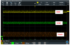
I have practical issue after received our chip prototype from foundry, the alternative drop in the supply voltage due to the switching activity of the digital clocked circuits in our chip,
I admit that supply line disturbance is expected practically due to switching currents that develop a voltage drop on the supply output resistance. However, I am using LAB supply voltage where I am surprised to see him suffer like this, it is not simple LDO circuit !!
What I need to conclude, using an ideal voltage source is not the right when simulating Mixed-signal IC with Cadence (or any other type of simulation), for example, I have the same simulation setup of the measurement and I see that switching activity has zero effect on the supply voltage (ideal voltage source) in my simulation results.
Since I want to learn from my practical results and to make a more realistic simulation with Cadence in the future, I would ask for you suggestion for using the ideal voltage supply in the circuit simulation, like do I need to connect a small resistor in series to represent the output resistance. What else I can consider to make the switching effect predicted by simulation.
Thank you in advance for your help
Best Regards


