cupoftea
Advanced Member level 6

Hi,
We are doing 300W isolated Synchronous Pushpull, 24vin, 32vout, 225khz. PCB screwed in bottom of Alu enclosure. FETs are surface mount. 4 layer PCB. No daughter boards.
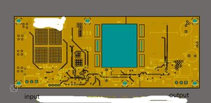
The attached shows the layer 2. All of that copper pour (yellow) is the same net as chassis.
You can also see where the planar transformer goes (the blue bit). You can also see the 6 screwholes by which the PCB screws into the Alu enclosure.
There 6 Y caps…
2 Y caps connect input ground to chassis connected coppe
2 Y caps connect input power to chassis connected copper
2 Y caps connect output ground to chassis connected copper
There is an output common mode choke but no input common mode choke.
Question…..
1…Why has a whole PCB layer been devoted to chassis?…..it is directly over the bottom mounted FETs…..and so the FET switching nodes will be pumping common mode noise into the shown chassis copper pour. Do you agree this chassis copper pour should not be there?

