Continue to Site

Welcome to EDAboard.com

Welcome to our site! EDAboard.com is an international Electronics Discussion Forum focused on EDA software, circuits, schematics, books, theory, papers, asic, pld, 8051, DSP, Network, RF, Analog Design, PCB, Service Manuals... and a whole lot more! To participate you need to register. Registration is free. Click here to register now.

Biasing the amplifier with high current mirror ration

Status
Not open for further replies.

Junus2012

Advanced Member level 5
Joined
Jan 9, 2012
Messages
1,552
Helped
47
Reputation
98
Reaction score
53
Trophy points
1,328
Location
Italy
Activity points
15,235
Hello,

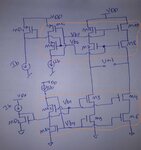
Following my formal post, I am trying to bias the core amplifier by means of biasing current mirror like shown in the image below
folo.jpg

As you see, Mx1-Mx4 are the bising mirror to the core amplifier (folded stage),

To save power, I am trying to make Ib less than the needed current in the amplifier then I rise it by means of the mirror ratio, for example I choose mirror ratio of 4,

My question, is it possible to increase the mirror ratio like to make it 10 ? I read somewhere that as more we increase the mirror ratio as more we have less aqurate mirror, is that true ? what is the preferable or reasonable ratio you would suggest

thank you very much
 

If you make all of the "unit fingers" the same then ratio
ought to hold. But trying to match a W=1 to a W=10
single stripe, is not good. Use W=1:W=1_M=10, and
DC match ought to be normal.

But high ratio and low pilot current can make the rack
"soggy" and less able to buck high frequency power
supply activity. Pilot device Rds(on) and rack total
Cdg, Cgs, Cbs tell you a corner frequency above which
"other actors" may meddle with the bias current and
potentially degrade HF PSRR.

Dear freebird,

Thank you for your reply,

I usually and always match with the same unit fingers, by making common unit size transistor and construct the targetted ratio,

I am sorry, forgive my poor understanding but I was lost after that in you explanation, did you suggest if I match with the same unit size then any ratio will be no problem ? I just found in Behzad rezavi book that he suggests to use biasing current between fifth to tenth of the amplifier current,
However, I find your practical notes by experience is more practical to consider than text book,
do you think current raio of 5 is good to cover many other aspects like you mentioned about PSRR

thank you once again
 

My question, is it possible to increase the mirror ratio like to make it 10 ? I read somewhere that as more we increase the mirror ratio as more we have less aqurate mirror, is that true ? what is the preferable or reasonable ratio you would suggest

Lets assume you have a 10uA perfect current from somewhere. And then you have two cases:
case 1# You do a 1:1 mirroring.
case #2 You do a 1:10 mirroring.

The relative accuracy (i.e standard deviation of the mirrored current / mirrored current) will be better in the second case.

But a higher mirroring ratio means larger number of multipliers, more parasitic capacitances and almost always poorer PSRR.

Also don't forget about random noise.

Dear vivekroy
Nice to see you again active with my post

Could you please expalin me why the accuracy of the second case (mirror 1:10) is more accurate than 1:1 ?
 

Hi Junus,

Hope you are well. Sorry I was busy with work and the current pandemic does not help xD

Take a look at the following figure
image.png

Vth mismatch of a transistor is given by Avt/(2WL)^0.5. However, this is the standard deviation (referred to as SD later in the answer) of Vth of a large number of transistors.
The standard deviation of Vth mismatch between two transistors of size W/L and mW/L is going to be given by [Avt/(2WL)^0.5] * (1+1/m)^0.5

SD{Imirror} ~ m*gm* [Avt/(2WL)^0.5] * (1+1/m)^0.5

==> SD{Imirror}/Imirror = { m*gm* [Avt/(2WL)^0.5] * (1+1/m)^0.5 } / {m*Ibias}

==> SD{Imirror}/Imirror = { gm* [Avt/(2WL)^0.5] * (1+1/m)^0.5 } / {Ibias}

Note that gm is the gm of the diode device.

To reduce the impact of mismatch, its always a good idea to decrease the gm/Id as much as possible (i.e. saturation region as opposed to sub-threhold region) but the tradeoff is always voltage headroom.
 
Dear viveroky,

I am fine and I hope you too doing well
I will study your derivation carefully, I think the source is book of "Art of analog layout",

You also linked the behavioural to the PSRR, so higher ratio is giving us these properties

1. less power dissipation
2. better matching
3. poor PSRR (which I still doesnt know why ?)

could you please then suggest a general rule of thumb for choosing the ratio, for example I will avoide biaising my amp from a current mirror of 1:1, nor I will go for high ratio like 1:10, I am thinking of moderate solution like 1:5,

what is your opinion

thank you once again and hope always see your valuable notes on my posts
 

Yes, with higher mirror ratio the relative accuracy dI/I is better but not much. If sigma of the 1x transistor Vt variation is Av/sqrt(WL), the sigma of the dI/I for 1:m mirror (that is I=m*Iref) is (gm/Iref)*[Av/sqrt(WL)]*sqrt((m+1)/m), where gm is the transconductance of the 1x device having current of Iref obviously. As you see if we have 1:2 mirror we have that last factor equal to 1.22 and if it is 1:20 mirror that factor is 1.02 which is about 20% better relative accuracy. Also, if we just look at the absolute accuracy, not the relative one, then variation increases proportional to m*sqrt((m+1)/m).
Noise of the output current also increases with increasing the mirror ratio but noise with respect to the output current actually decreases. Sort of an SNR metric and follows the same logic as for the relative accuracy with mismatch.

- - - Updated - - -

Oh, I just saw that Vivekroy actually answered the question. Sorry for the double-up.
 
Dear Suta,

Nothing is doubled answered, for me your answers like having information from different books, all are appriciated and thank you all for your contribution,

it will be useful to me if you refer me to the reference source to include it in my report,

I see from your comments that current mirror accuracy at least is not going to degrade with larger mirror ratio,

This leads me to a logical question,

usually in most of the books or papers I read, for example the differential pair transistors of the op-amp is biased with Iss= 100 µA, and the designer provide this value by a current mirror of 1:2, means he supply 50 µA from the biasing circuit. So why not using factor 1:10 and supplying it with 10 µA, this should save more power

Secondly, your kind explanation doesnt included the layout imperfection, I think layout mirror with less ratio will result in a better layout than with larger ratio

Thanks
 

When you do mismatch in schematic you are kind of limited to what the models assume for the layout effects in the devices. Sometimes the models include no layout effects. When you do the layout you can take care of all layout effects like placing dummies, having all surroundings for the transistors the same, etc. Thus you at least take care of systematic mismatches. As for the random mismatch, it should be the same as in schematic, it is just statistics.
I don't know why in papers you've read they use 1:2 mirror ratio. I've seen even 1:10 and more. One explanation could be that if the mirror is used to bias diff pairs, then you care for absolute accuracy because this results in absolute accuracy of the gm for example and from there absolute accuracy in the unity gain frequency. Absolute accuracy is better for small mirror ratios.

I can't provide reference for what I said in my previous post. I just did the calculations on paper and checked them in simulation. But I'm pretty sure it is somewhere in some books. Maybe other people know in what books you can find it.
 

    Junus2012

    Points: 2
    Helpful Answer Positive Rating
Dear friends , I am mixing between relative and absolute accuracy of the current mirror
 

Dear friends,
I have biased the cascode transistors of the op-amp from a biasing current mirror with 1:10 and it is working fine

before this step I have tested a wide swing cascode mirror, one with mirror ratio of 1:5, and the other with 1:10 to give the same Io from Iin (means changing Iin to get the same Io result in either cases), please refer to my first post picture, where I implemented it with these values

Case 1 (1:5): Ib = 20 µA, MX1, MX2 = 60 µm/1 µm, M7-M10 = 300 µm / 1 µm, Iout = 100 uA

case 2 (1:10): Ib = 10 µA, MX1, MX2 =30 µm/1 µm, M7-M10 = 300 µm / 1 µm, Iout = 100 uA


The result are almost identical, so to save power I selected the ratio of 1:10 and continued in the design,
 
  • Like
Reactions: t4_v

    t4_v

    Points: 2
    Helpful Answer Positive Rating
Don't forget to match parasitic resistances on the source (ground) net, so that 10x (or whatever the ratio) difference in currents produce the same voltage drop (metal debiasing), to produce the same Vgs effective gate voltage.
Especially in advanced nodes, parasitic resistances are very high, and these effects can be very important.
 
Status
Not open for further replies.

Part and Inventory Search

Welcome to EDABoard.com

Sponsor

Back
Top