Continue to Site

Welcome to EDAboard.com

Welcome to our site! EDAboard.com is an international Electronics Discussion Forum focused on EDA software, circuits, schematics, books, theory, papers, asic, pld, 8051, DSP, Network, RF, Analog Design, PCB, Service Manuals... and a whole lot more! To participate you need to register. Registration is free. Click here to register now.

Flyback Airgap Doubts?

Status
Not open for further replies.
(i'll say nothing, i got my brains smashed up once when asked to design Cuk's single stage isolated PFC'd Cuk converter for an EV charger at 3000W...after a week, all i had was a sim which didnt seem to work that well, so i got taken off the job....i seem to remember they also wanted it bidirectional...could be wrong about that bit)
sorry to go off topic....OP please send latest schem etc and ill take a look
 

Isolated PFC Cuk @ 3kW is only for the power electronics engineer with 15+ years of solid experience ...
 
  • Like
Reactions: treez

    T

    Points: 2
    Helpful Answer Positive Rating
if i recall, cuk converters need to be individually tuned by gapping the
inductor one at a time
please forgive me if i remember incorrectly
 
  • Like
Reactions: treez

    T

    Points: 2
    Helpful Answer Positive Rating
you recall incorrectly ... tuning, as such, was only ever required if you wished to get close to minimum current ripple on the coupled inductor AND transformer variants - it is possible to design the coupled chokes - such that very close to minimum ripple is achieved without adjustment.
 
  • Like
Reactions: treez

    T

    Points: 2
    Helpful Answer Positive Rating
If I want to avoid the RCD snubber from the primary, what are my options?
 

its a flyback so you cant avoid the RCD clamp....if you dont like it you could do a two transistor forward instead.
 

no @treez i didnt mean to completely remove it ,, I was talking about an alternative like zener clamp etc
 
  • Like
Reactions: treez

    T

    Points: 2
    Helpful Answer Positive Rating
Thats probably the only other one.....the zener or TVS clamp.....there is the RCDZ clamp which reduces rcd clamp dissipation in light or no load.
Power integrations used to have app notes on it.
There's also the RCD clamp with a slow diode so that the leakage current can ring back out of the rcd capacitor and therefore not cause so much dissipation in the rcd resistor....it was another power integrations invention but they seem to be distancing themselves from it now.
 

Well.. Got stuck in the Corona virus Lock down... Unable to obtain any gapped cores.. So I still have to wait.
One of the youtube videos got me to this software
so for the moment I dropped the TI design and tried this new one
12v_3A_01.jpg

Then after soldering complete.. the unit started working...
initial output 12.2volt (no load -- but i have a 100ohm/2watt resister soldered at the output; not included in any load calculations)
Then at 150ma load - 12.0v
500 ma load - 11.6v
900ma - 10.6v
1.5amp - 10.6v
I stopped here.
The software show duty cycle of around 25%

Until then I was using a UC3845 (50% duty cycle)
RT=1nf; CT=9Kohm. => 100 khz (95k to be precise)(It is actually running at 200khz, achieves

the 50% duty cycle by blanking alternate cycles)

so now I changed the CT to 18K and replaced the UC3845 with UC3843 (the 100%

duty cycle one)
I connnected a 60w bulb in series at input , turned the unit on
nothing at the output, the 60w lamp is somewhat bright

Again I replaced things to previous (9k to 18 k ; 3845 to 3845)
now it works.

so what is happening .. the thing is some how working with 3845 as the Duty

cycle is limited to 50%
and when the 3843 is connected it runs at 100% thereby shorting the MOSFET?

The problem is with my transformer..??????
I am planning to use a transformer (for testing ) from already available 3amp supply (chinese RCC)
I have 12v - 1A,2A,3A... with no IC, only transistors.
Anyone know for what frequencies are this transformers designed for?
 

if you have two core halves you can put the gap right thru - i.e. if gap = 2mm, gap RT ( right thru ) = 1mm
 

Anyone know for what frequencies are this transformers designed for?

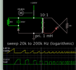
Is the primary about 1mH (in your flyback calculator)? Here's a simulation of the flyback concept.
Frequency sweep 20-200 kHz seems to be the range that reveals reasonable performance.

transformer 1mH pri flyback waveforms demo sweep 20-200 kHz.png

65 kHz is midway through the run. Notice at slower frequencies your core needs higher saturation rating.
 

Is the primary about 1mH (in your flyback calculator)? Here's a simulation of the flyback concept.
Frequency sweep 20-200 kHz seems to be the range that reveals reasonable performance.

View attachment 159014

65 kHz is midway through the run. Notice at slower frequencies your core needs higher saturation rating.

Okay ... I will try some frequencies...
Any idea about what could have happened when I replaced UC3845 with UC3843
 

Hi,
I haven't been here for sometime. Feels good to be back.

...
Any idea about what could have happened when I replaced UC3845 with UC3843
At the startup of switching converters, due to the dynamics, the duty cycle starts at the maximum value and the control loops wrestles to bring it to the design value. With the UC3845 the duty cycle starts at 50%, and with the UC3843 it starts at 100%. There are known concerns with this duty cycle saturation. One of the concerns is that the duty cycle can stay saturated for a long period of time before the controller is able to bring it under control. To take care of it, you have to incorporate soft-starting in your desig so that the duty cycle starts at 0% and ramp up slowly to the design duty cycle.

Telling exactly what is wrong with your design is not very straightforward as an improperly design control loop may also cause this type of issues where your frequency response deteriorate with decreased load.

I'd suggest you post your schematic so we can take a look.
 

...
One of the youtube videos got me to this software
so for the moment I dropped the TI design and tried this new one
View attachment 159012

Then after soldering complete.. the unit started working...
initial output 12.2volt (no load -- but i have a 100ohm/2watt resister soldered at the output; not included in any load calculations)
Then at 150ma load - 12.0v
500 ma load - 11.6v
900ma - 10.6v
1.5amp - 10.6v
I stopped here.
...

With this, I'd suggest that you use a lower Rsense resistor value and check again.

What resistor value did you use as Rsense when you got this result?
 
Sounds like, yes, hitting Vmax on the Isense resistor earlier with load, or IC is at max pwm - or the power source is sagging ( what is it ? ) also complete ckt please - else all is guesswork ...

- - - Updated - - -

output cap needs to be at least 470uF, speed up ckt on f/back loop not needed ...
 

Status
Not open for further replies.

Similar threads

Part and Inventory Search

Welcome to EDABoard.com

Sponsor

Back
Top