Continue to Site

Welcome to EDAboard.com

Welcome to our site! EDAboard.com is an international Electronics Discussion Forum focused on EDA software, circuits, schematics, books, theory, papers, asic, pld, 8051, DSP, Network, RF, Analog Design, PCB, Service Manuals... and a whole lot more! To participate you need to register. Registration is free. Click here to register now.

How to solve the circuit

Status
Not open for further replies.

electronicsman

Full Member level 5
Full Member level 5
Joined
May 4, 2012
Messages
291
Helped
11
Reputation
22
Reaction score
12
Trophy points
1,298
Activity points
3,737
I am trying to solve the circuit. I am not posting the full question but my doubt is inductor seems to be directly across the voltage source without resistance R in the loop. Is it possible? I have to find out when the fuse breaks. Please advise.
schematic1.JPG
 

Hi,

It is possible.
But don't know whether it makes sense.

We see the circuit ... and it could be built in reality. That's all I can say.
Maybe more information in the complete text.

Klaus
 

it is a problem in a textbook
its function is not to represent a real circuit, but to help you develop an understanding
of how circuits works and demonstrate both good and bad practices.

note the hint about the equations that apply and don't apply
look at equation 30-41 and determine why it doesn't apply
look at equation 30-39 what does it tell you, and why would the questions say re-think it?

the various symbols in an equation are not just placeholders for numbers
they have physical meaning and their combinations have physical meaning.

(i.e. meaning in physics and therefore meaning in electrical engineering)
 

hint: If the fuse is assumed to have zero resistance, the value of R is unimportant. It's value would only have an effect AFTER the fuse 'blows' which is not part of the question. Your task is to sketch a graph of current flow through an inductor when it sees a step change in voltage applied across it.

Brian.
 

The equation 39 is equa39.JPG and the equation 41 is equa41.JPG. This is my attempt using equation 39 and making current i through R as 0, I get
Code:
L*di/dt = E; 
i = E/L*t ;
3 = 10/5*t;
t = 1.5s;
After 1.5s the fuse blows.
 

so why doesn't equation 30-41 apply?

what did re-thinking equation 30-39 lead you to?
specifically, what did you change and why?

what is the difference between the two equations in the textbooks hint?

what does this tell you about choosing an appropriate
concept and/or equation to solve a problem?

the problem asks for a numerical answer, but you had
to answer all these conceptual questions to get there
 
The equation 39 is View attachment 157138 and the equation 41 is View attachment 157139. This is my attempt using equation 39 and making current i through R as 0, I get
Code:
L*di/dt = E; 
i = E/L*t ;
3 = 10/5*t;
t = 1.5s;
After 1.5s the fuse blows.

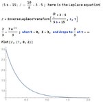
I don't think you got a handle on what is happening. The coil has no resistance to the current, so the fuse exceeds the 3 amp limit immediately and blows. At t=0, we have an initial current of 3 amps in the loop powered by the initial current in the coil. As the magnetic field weakens, the battery takes over and keeps the the loop current at 2/3 amps. This happens after about 1 and 1/2 seconds. The Laplace equation and plot is show below.

Capture.JPG

When t=0, I=3, and when t= infinity, I=2/3.

Ratch
 
Last edited:

since the current in the circuit is zero before the switch is closed, (t = 0-) it must also be 0 after the switch is closed.
the current in an inductor cannot change instantly, the voltage across the inductor can change instantly
therefore the current is not 3A at t = 0+ (immediately after the switch is closed)

the problem specifically says eq 30-41 does not apply and one needs to modify 30-39
since R = 0 ohm, electronicsman modified the equation as necessary
i think he did the math appropriately

considering the equations called out in the problem, i do not believe the text is at the level
where laplace transforms used, in fact, i do not think they have been introduced yet.

@ratch
the left side of your first line is the impedance times the current, so the right side has to be the voltage
it has been a while since i used laplace transforms
kindly remind me how you got the right side of your first equation

it looks like a second order, since if you multiply by s, you get s^2 ??

it is clear that after the fuse blows, the current is limited by the resistor
and the voltage drop across the inductor eventually goes to 0
and the current is 2/3 A
 

The coil has no resistance to the current, so the fuse exceeds the 3 amp limit immediately and blows.
Ratch
But this is against the property of the inductor. The current in an inductor cannot change immediately it raises exponentially.
 

Hi,

I agree that thecurrent of the coil starts with zero.
But this is against the property of the inductor. The current in an inductor cannot change immediately it raises exponentially.
But why "exponentially"?

L = V x t / I in units: H = Vs/A.

Now the voltage across the coil is constant. When we also expect the inductance to stay constant (non saturating).

Then V/L = I/t ....in units": V/H = A/s ... replace H with Vs/A then V/(Vs/A) =A/s
V/L is constant, thus I/t needs to be constant, too.

It means a linear rise rate of current.
Example :
2A after 1s --> 2A/1s = 2A/s
4A after 2s --> 4A/2s = 2A/s
6A after 3s --> 6A/3s = 2A/s
8A after 4s --> 8A/4s = 2A/s
...the rise rate is constant 2A/s

With a real coil there are two major issues making it nonlinear:
* coil saturation
* series resistance

Klaus
 
Hi,

It means a linear rise rate of current.
Example :
2A after 1s --> 2A/1s = 2A/s
4A after 2s --> 4A/2s = 2A/s
6A after 3s --> 6A/3s = 2A/s
8A after 4s --> 8A/4s = 2A/s
...the rise rate is constant 2A/s

With a real coil there are two major issues making it nonlinear:
* coil saturation
* series resistance

Klaus

The reason i said exponential because of the current equation in the inductor
equa41.JPG

L = V x t / I
I think it should be
equa39.JPG
If you assume constant current then dI/dt will be 0.
 
Hi,

The reason i said exponential because of the current equation in the inductor
This is for true coil with series R....
this case I've already mentioned, although not given in the circuit..Then the L's series R limits the current. I see no series R that can limit the current, thus one has to assume unlimited current.

And then it is "1/exponential", which is called logarithmic (you can see the negative sign in front of t in the exponent)
e^(-t) = 1/(e^t)
* exponential results in infinite value and infinite rise rate
* whereas logarithmic results in a constant, limited value and (close to) zero rise rate

If you assume constant current then dI/dt will be 0.
I never assumed constant current.

Klaus
 
@ratch
i made a mistake
the left side of your first equation, 5s + 15 ignored the fuse
the resistor is shorted at t = 0- and is still shorted until the fuse blows
therefor the 15 should not be part of the impedance for t < fuse blows

please excuse me for being annoying
 

To the Ineffable All,
If there was a solid wire instead of a fuse, the current would try to go toward to infinity. It would whiz past 3 amps in a blink of an eye, so to speak. So the fuse initializes the current in the coil at 3 amps. From there on it is a simple differential equation involving a voltage, coil, resistor, and an initial current as I showed above.

Ratch
 
According to problem text, the switch is closed at t=0. According to usual understanding, the initial condition has to be calculated with open switch. Hence current starts linearly from zero, as calculated in post #6.

In SPICE simulator terms, we would specify Vinitial=0, Von=10, tdelay=0.
 

According to problem text, the switch is closed at t=0. According to usual understanding, the initial condition has to be calculated with open switch. Hence current starts linearly from zero, as calculated in post #6.

In SPICE simulator terms, we would specify Vinitial=0, Von=10, tdelay=0.

Yes, the current is zero at t=0, and rises to 3 amps in an infinitesimal amount of time when the fuse blows. How long does it take current to rise to a finite value when a voltage source is shorted at t=0?

Ratch

- - - Updated - - -

But this is against the property of the inductor. The current in an inductor cannot change immediately it raises exponentially.

See post #15. Without resistance, there is no finite time-constant or definite exponential curve. The upper current limit is infinity and the time to reach a finite current is indeterminate. While current in an inductor cannot change immediately, it can change very fast.

Ratch
 

Hi,

Without resistance, there is no finite time-constant
Correct, no time constant,
but a constant current rise rate = current rises linearly ... in this case with 2A/s.
Thus it takes 1.5s to get 3A...

Klaus
 

Hi,


Correct, no time constant,
but a constant current rise rate = current rises linearly ... in this case with 2A/s.
Thus it takes 1.5s to get 3A...

Klaus

OK, lets figure it out.

Capture.JPG

You are right. I stand corrected

Ratch
 

Status
Not open for further replies.

Part and Inventory Search

Welcome to EDABoard.com

Sponsor

Back
Top