Continue to Site

Welcome to EDAboard.com

Welcome to our site! EDAboard.com is an international Electronics Discussion Forum focused on EDA software, circuits, schematics, books, theory, papers, asic, pld, 8051, DSP, Network, RF, Analog Design, PCB, Service Manuals... and a whole lot more! To participate you need to register. Registration is free. Click here to register now.

[SOLVED] uc384x PWM DC-DC converter not regulating.

Status
Not open for further replies.

codemaster11

Advanced Member level 4
Full Member level 1
Joined
Sep 2, 2019
Messages
115
Helped
9
Reputation
18
Reaction score
7
Trophy points
18
Activity points
1,220
Capture.JPG
6.1scm.jpg

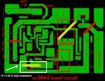
the input to the circuit is Vin = 9vdc. output of the converter is 48vdc but the regulator trimmer is not working.

connecting the trimmer with the Vfeb pin#2 of the oscillator stop the oscillator with no output voltage. disconnecting the trimmer

oscillator starts with Vout = 48vdc. i use a jumper instead the current sense resistor with resistance less than 0.06ohm.

as indicated by arrow in the pcblayout. is it the problem with jumper at the source of the MOSFET?
 

Hi,

in the datasheet there is a chapter "Design considerations".
If you don´t keep on them you should not be surprised if it does not work.

--> your PCB layout is not suitable. It needs a solid GND plane.. and you need to take core of the other design informations.

Klaus
 

OK - layout is ill considered - but to get it going - try the following;

1) 1uF MLCC 50V across R6

2) put 1206 size 330pF for C4 soldered directly from pin 3 to 5 pins

3) Add 1uF to C7

4) make R4 22 ohm

5) Make R1 => 1k in series with 47nF

6) Report back when all changed and tested ...
 
Hi,

First of all, your choice of divider resistors to derive Vref of 2.5V from 48V output is not adequate. Even if you adjusted the trimmer to the bottom, you'd have 2.697V whereas you need 2.5V. I'd advise to not use a pot. Make simple voltage divider calculations to derive 2.5V from 48V and use fixed resistors.

For Rsense, we can't say much for the info you have given us. You haven't told us anything that portrays your peak inductor current value. Moreover, a fixed resistor (not wire wound) will be better suited for current sensing.

- - - Updated - - -

Also, I do not have time to make calculations for your converter but your input and output specs has caught my attention. Can you explain those?

What about UVLO?
 

Yes, when the pot is set to the bottom - you will get 44.5Vout, and 4.04V out when the pot is turned to the top - in your schematic ...

- - - Updated - - -

from your other thread on this topic:
400 watt which mean 15v/25A input and 36v/12A

Do you have a power supply that can really provide 9 or 15VDC at 25A ...? if not you cannot test properly ...

- - - Updated - - -

bleeder resistors on the Vout a good idea say 680 ohm 5W to pull the volts down at no load - else there will be a pulse at start up - the Vout will fly up to > 44V and stay there for a long time all by itself ...

hence soft start a very good idea on your control ckt
 
  • Like
Reactions: FvM

    FvM

    Points: 2
    Helpful Answer Positive Rating
Hi,

You need to implement a voltage divider at the output to derive a voltage that is equal to the reference voltage of the error amplifier.

Consider using 91k and 5k with 1% tolerance or better.
 

i want fixed Vout = 14vdc from Vin = 9v-25vdc not 48vdc. possibly it may be the problem

of pin#2 Vfb = 2.5v which in this circuit is not 2.5vdc. i want 14vdc output but it give 48vdc how to reduce this voltage to 14vdc.

by reducing numbers of turns of the ferrite inductor?
 

i will try it with 10R/10watt resistors in series but i don't have any specific rated load of 48vdc.

how to decrease the output voltage to 14vdc. the output regulator trimmer not working to decrease it

to 14vdc also it stops oscillators?
 

you cannot have Vout < Vin due to the diode - you need to have a load on the o/p to test properly ...
 

the input to the circuit is Vin = 9-25vdc. the output is 48vdc. i need to know the reason why the oscillator

stops when i connect the voltage divider trimmer to Vfb pin of uc3843. voltage regulation with load is not the problem.

i didn't test it with load yet. i also know that the voltage at Vfb pin is not 2.5v in my circuit. but i didn't understand the reason of

of oscillator stopping when i connect voltage divider trimmer with Vfb pin. if oscillator stops when voltage at pin # 2 of uc3843

greater than 2.5v then certainly it will stop. my circuit have Vfb = 3.1v.
 

Your Vfb should be 2.5V. The feedback pin is the inverting terminal of the error amplifier. The noninverting terminal is connected to a 2.5V reference.

- - - Updated - - -

Unfortunately, your combination of R7, R8 and R9 cannot give your 2.5V at Vfb. I have already calculated for you the resistor values that would give you 2.5V. See post #6.

- - - Updated - - -

The above info is for output voltage of 48V.

If you are saying that you want an output voltage of 14V with an input range of 9-25V, then you need a buckboost topology. Tge boost topology cannot buck in any circumstance.
 

without load and soft start it will always overshoot at startup on the output and stay there for ages - this is your problem, if you choose to ignore all the advice above you will find it difficult to progress
 

Codemaster, please change topology.

Se SEPIC, cúk and noninverting buckboost topologies.
 

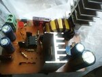
Photo0417.jpg

the components listed within post#3 works fine with my design. the circuit now works as regulated boost converter

with output voltage greater than the input. i put the divider resistor of 86k with 100k trimmer & fixed 4.7k for 48vdc. to get 2.5v at

Vfb pin of uc3843.

-----------------------
--thanks Easy Peasy
 
Last edited:
That's about double of what I gave you (91k & 5k). With 100k+86k+4.7k combination, you are using resistances somewhere between 180k and 181k for the upper divider resistor and 9.9k and 10k for the lower one. You could even get this ratio with replacing your initial 10k pot with a 20k pot and then trimming as required.

By the way, if you are designing for mass production, you will have to do trimming in all the supplies with a pot in the divider. That is why I advised you to go with 91k and 5k with 0.1% tolerance or better.

You said that at the output you wanted 14V and not 48V. You seem to be very satisfied with 48V output now. How so?

- - - Updated - - -

Anyways, if you have found the solution to the problem, then there's no need for me to look anymore.

Congratulations!
 

**broken link removed**

i made my own voltage divider calculator for getting fixed voltage by using excel worksheet.

and set the 100k trimmer by shorting its variable and one fixed pin to get 86k in series

with 4.7k to getting 2.5v at Vfb pin, as shown in calculation. i only want the trimmer to be used to change the O/P voltage > I/P voltage

to any value upto 48vdc and the trimmer works correctly. that's my point.

**broken link removed**

the calculation for 2.5vdc at Vfb pin in post#6 is also correct.
 

Status
Not open for further replies.

Similar threads

Part and Inventory Search

Welcome to EDABoard.com

Sponsor

Back
Top