Continue to Site

Welcome to EDAboard.com

Welcome to our site! EDAboard.com is an international Electronics Discussion Forum focused on EDA software, circuits, schematics, books, theory, papers, asic, pld, 8051, DSP, Network, RF, Analog Design, PCB, Service Manuals... and a whole lot more! To participate you need to register. Registration is free. Click here to register now.

Audio amplifier on PCB error. Ports of opAmp shorted.Can't find the reason why?

Status
Not open for further replies.

rhonny

Newbie level 5
Newbie level 5
Joined
Jun 13, 2019
Messages
9
Helped
0
Reputation
0
Reaction score
0
Trophy points
1
Visit site
Activity points
78
Hello

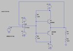
I am working on audio amplifier for my project.I'll share the image below post.I ran the design on LT Spice. It seems to work while simulating but somehow when i designed it on pcb,it doesn't work. My Op Amp and transistors heat a lot and some ports of my op amp are short circuited. I am not able to find the reason. Can anyone please help me. The resistance of the load would be around 33 mOhms and i want around 1 ampere current through it.

this is the link to image

JTrUsuT.png
 

A few points come to mind right away --

1) why such high power supply voltages ? you've got +/- 30 volts.
2) the feedback for opamp should be taken from before C1, not after.
3) What are the actual components you have used ? Opamp, diodes and BJT ?
4) Just to clarify - is your load 33 mOhms (which is 0.033 ohms) or is it 33 ohms ?
5) By 1A current do you mean Ipk-pk, or Irms, or what ?

once we get this information we can proceed to help solve your problem.
 

1)if i don't use +/-30,my o/ voltage gets clipped.
2)thank you,i got this one.
3)Op Amp is l272, diode is 1N4003 and bjt is TIP 3055(npn)
4)it's 33 mohms,but it would heat my sample too much so i'll add 33 ohms in series
5)its peak to peak
 

Attachments

  • l272.pdf
    892.1 KB · Views: 145
  • TIP3055-D.pdf
    104.8 KB · Views: 138

If your load is truly only 0.033 ohms, then you need only 0.033 Vp-p (33mVpp) to get your desired current of 1 Amp p-p
You can reduce all your voltages etc etc accordingly.

In fact, here is a reduced/ simplified circuit you could use instead.

circuit1.JPG

Voltages reduced to just +/- 3v on output stage. Diodes removed, coupling cap removed (its a dual supply - no need), feedback is unity.
The input signal is reduced.
BJT's in this spice example are not adequate for peak current & power dissipation. So you have to choose differently. But reasonably high hFE and fT with approx > 1W dissipation and >1A peak current can be easily found.
Key point to note is the opamp features necessary. Not necessarily the one in this example. You need high GBW and definitely need high slew rate ! At least 10V/uS or more.

Here are the waveforms produced --

waveform1.JPG

Hope this helps!
 
  • Like
Reactions: rhonny

    rhonny

    Points: 2
    Helpful Answer Positive Rating
Whenever doing analog simulations it is appropriate to perform a Monte Carlo analysis, or something similar such as adding variation in the circuit parameters, such as a Hfe's discrepanciy. BTW, for audio amplifiers one would expect a load in the range of ohms, not miliohms.
 

... BTW, for audio amplifiers one would expect a load in the range of ohms, not miliohms.

That's correct, which is why I asked for confirmation about the strange load value. Clearly the application is not pure audio amp but some other purpose which OP has not revealed as yet.
 

If your load is truly only 0.033 ohms, then you need only 0.033 Vp-p (33mVpp) to get your desired current of 1 Amp p-p
You can reduce all your voltages etc etc accordingly.

In fact, here is a reduced/ simplified circuit you could use instead.

Voltages reduced to just +/- 3v on output stage. Diodes removed, coupling cap removed (its a dual supply - no need), feedback is unity.
The input signal is reduced.
BJT's in this spice example are not adequate for peak current & power dissipation. So you have to choose differently. But reasonably high hFE and fT with approx > 1W dissipation and >1A peak current can be easily found.
Key point to note is the opamp features necessary. Not necessarily the one in this example. You need high GBW and definitely need high slew rate ! At least 10V/uS or more.

Here are the waveforms produced --

Hope this helps!

Thanks for the circuit. I made this circuit and somehow port7 of PIN is connected to port8,2, and 4.(doesnt matter what op Amp i use). They are always connected . As for your question related to application of amplifier, I have to excite a membrane with the amplifier which requires a current of 1A and the function generator doesn't produce such high current.The membrane frequency of excitation goes upto 50kHZ ,that's why i can't use the amplifiers in market.

L272 maximal supply voltage is 28V, not +/- 28V.

Yes,thank you. I forgot to update the picture. I was providing about +/- 12 volts for L272
 

It would be better to have a consistent schematic with actual component values. The 33 mohm + 30 ohm point seems to contradict other specifications, you can't drive more than a few 100 mA into this load with +/- 12 V supply. Also base current sourced by 2.2k is far too low.

Nevertheless the circuit has no ability to damage a correctly connected L272. But there are some questions. Do you provide necessary power supply bypass capacitors for the power supply? How is the unused second channel connected?
 

I didn't use bypass capacitors.I don't know why i need it? I just left the pins for second channel open.Do i need to do something else with them?
 

High speed and power OPs without bypass capacitors are likely to self-oscillate. Also floating inputs may cause problems. You can e.g. connect the unused channel as voltage follower, out to vin-, vin+ to ground. Or bias it so that the output is driven into saturation.
 

If your load is truly only 0.033 ohms, then you need only 0.033 Vp-p (33mVpp) to get your desired current of 1 Amp p-p
You can reduce all your voltages etc etc accordingly.

In fact, here is a reduced/ simplified circuit you could use instead.

View attachment 153687

Voltages reduced to just +/- 3v on output stage. Diodes removed, coupling cap removed (its a dual supply - no need), feedback is unity.
The input signal is reduced.
BJT's in this spice example are not adequate for peak current & power dissipation. So you have to choose differently. But reasonably high hFE and fT with approx > 1W dissipation and >1A peak current can be easily found.
Key point to note is the opamp features necessary. Not necessarily the one in this example. You need high GBW and definitely need high slew rate ! At least 10V/uS or more.

Here are the waveforms produced --

View attachment 153688

Hope this helps!

This circuit doesn't provide 1 A. I get it that it works like voltage follower circuit but i don't get any current in the output,although input is same as output.

- - - Updated - - -

Thanks,yes,floating inputs were the problem. Now my output voltage is same as input by i am getting 0 current in load resistance.I don't get it how can it happen?
 

Thanks,yes,floating inputs were the problem. Now my output voltage is same as input by i am getting 0 current in load resistance.I don't get it how can it happen?
Which circuit are you talking about now? Post #1 or post #4?

- - - Updated - - -

Now my output voltage is same as input by i am getting 0 current in load resistance.I don't get it how can it happen?
Doesn't make sense. How do you measure?
 

Connected multimeter in series with load resistance!! but it gives no output. Still the input+(pin7) is connected to supply voltage(pin 2) and ground(pin 4). I checked the circuit connections multiple times but as soon as i connect power sources, these pins seems to be connected.I connected .1uF bypass capacitors to supply voltage and ground. I also connected unused channel as voltage follower.
 

Status
Not open for further replies.

Part and Inventory Search

Welcome to EDABoard.com

Sponsor

Back
Top