Continue to Site

Welcome to EDAboard.com

Welcome to our site! EDAboard.com is an international Electronics Discussion Forum focused on EDA software, circuits, schematics, books, theory, papers, asic, pld, 8051, DSP, Network, RF, Analog Design, PCB, Service Manuals... and a whole lot more! To participate you need to register. Registration is free. Click here to register now.

Pindiodes infront of LNA

Status
Not open for further replies.

akhilpaulv

Full Member level 2
Full Member level 2
Joined
Apr 20, 2013
Messages
136
Helped
7
Reputation
14
Reaction score
7
Trophy points
1,298
Location
Thrissur, India
Activity points
2,051
Hi all,
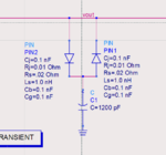
Why two pindiodes in opposite sides with capacitor used infront of LNAs ??
Frequency of LNA is around 60MHz

Akhil
 

I used PIN diodes as a T/R switch. They were in front of my LNA. It is also possible that your PINs are being used as limiters to prevent overloading your LNA. Without a schematic, we can only guess.
 
I used PIN diodes as a T/R switch. They were in front of my LNA. It is also possible that your PINs are being used as limiters to prevent overloading your LNA. Without a schematic, we can only guess.

Hi thankyou for your replay . When i put the model in the simulation software its gives a junk value . ATTUNATOR.PNG
 

So you've got a model of a PIN diode. Where is the schematic for your circuit?

With what you show, nearly 100% of the signal is being shunted to ground, but without a schematic, this is only a guess.
 
Status
Not open for further replies.

Similar threads

Part and Inventory Search

Welcome to EDABoard.com

Sponsor

Back
Top