Continue to Site

Welcome to EDAboard.com

Welcome to our site! EDAboard.com is an international Electronics Discussion Forum focused on EDA software, circuits, schematics, books, theory, papers, asic, pld, 8051, DSP, Network, RF, Analog Design, PCB, Service Manuals... and a whole lot more! To participate you need to register. Registration is free. Click here to register now.

Reading channel B for HX711

Status
Not open for further replies.

mr_byte31

Full Member level 5
Full Member level 5
Joined
Oct 19, 2005
Messages
295
Helped
10
Reputation
20
Reaction score
8
Trophy points
1,298
Activity points
3,241
Hi All,

I make a small project. I use AVR to read load cell measurement using HX711.

I bought this board :
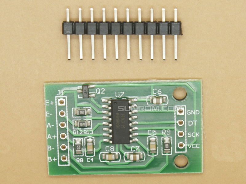
195_800.jpg


I read the datasheet but I couldn't get how to select/mulitplex between channel A or B for reading

datasheet : **broken link removed**

any idea?
 

hi 31,
The B channels is selected by sending 27 clock pulses during te data read sequence.
The Gain is fixed at 64.
E
 

Attachments

  • A02.gif
    A02.gif
    28.5 KB · Views: 328

I read this part in the document but still doesn't make any sense.

when clock is started, the bits are present on the Dout. Till now the IC doesn't know how many clock triggers it will receive.

how would the IC put the results on the Dout without knowing how many clocks it will receive !!! this is very confusing !
 

hi mr,
My understanding is the Channel is selected after the first Read, so sending 26 clock pulses will select Channel 'B' at a gain of 32.
The next 26 pulses will output Channel 'B' data.
Normally I use 25 pulses in order to select 'A' at 128 and a Arduino lib for the HX.

Which library are you using for you HX711 program code.?

Note the misprint on the datasheet between Fig #2 and Table 1, Channel select for 27 pulses.


E
 
what you said can be true but it is not in the datasheet :)
there is also another mistake on figure with pulses, they write channel B with different gains !
 

how would the IC put the results on the Dout without knowing how many clocks it will receive !!! this is very confusing !
what you said can be true but it is not in the datasheet :)
there is also another mistake on figure with pulses, they write channel B with different gains !
Seems like you didn't read the datasheet thoroughly. It's very clear about the number of clock pulses setting the parameters for the next conversion.

It's however unclear if 27 pulses select channel A (table 3) or B (figure 2). The first makes more sense.
 

Status
Not open for further replies.

Similar threads

Part and Inventory Search

Welcome to EDABoard.com

Sponsor

Back
Top