Continue to Site

Welcome to EDAboard.com

Welcome to our site! EDAboard.com is an international Electronics Discussion Forum focused on EDA software, circuits, schematics, books, theory, papers, asic, pld, 8051, DSP, Network, RF, Analog Design, PCB, Service Manuals... and a whole lot more! To participate you need to register. Registration is free. Click here to register now.

ADC input: What is the resistance?

Status
Not open for further replies.

julian403

Full Member level 5
Full Member level 5
Joined
Feb 28, 2014
Messages
254
Helped
1
Reputation
2
Reaction score
1
Trophy points
18
Location
Argentina
Activity points
2,105
ADC input: What are that resistance?

Hello All.

I need to sense 220 AC voltage signals with F28377S LaunchPad Development Kit. So for that, I'm going to use de differential 16 bit ADC but I have a question related with the input impedance. As you can see in the next picture.

Capture.PNG

My question is, The resistance Rs, are the Cooper path resistance from the board's input to ADC input?
 

Re: ADC input: What are that resistance?

hi j,
No, Rs is the output resistance of the AC source.

E
 
Re: ADC input: What are that resistance?

Thanks for the reply. But What happens if the source's impedance is not 50 Ohms? for example. I'm going to connect the distribution voltage with a resistance of 1 MOhms, so with the 1400 Ohms ADC resistance there will be a voltage divider.
 

Re: ADC input: What are that resistance?

hi,
The Ch capacitor [Chold] has to charge to the voltage level of the source in order to get a correct ADC reading for the Vsource voltage.
If the Sample time is short and the Input resistance between the Vsource and Ch is 'high', the ADC reading will be low because the Ch will not fully charge to Vsource.

What is the sample time and and at what rate is Vsource changing.?

E
 
Re: ADC input: What are that resistance?

You should have a resistive voltage divider in any case. Does the ADC datasheet specify a maximal source impedance > 50 ohm. If not, you'll better use a buffer amplifier.

A true differential source is usually expected. Your divided 230 V source doesn't necessarily provide it.
 
Re: ADC input: What are that resistance?

hi,
The Ch capacitor [Chold] has to charge to the voltage level of the source in order to get a correct ADC reading for the Vsource voltage.
If the Sample time is short and the Input resistance between the Vsource and Ch is 'high', the ADC reading will be low because the Ch will not fully charge to Vsource.
Thank you, I get it now.

The sample time is 1 micro second. and the voltage source has a frecuency of 50Hz.

Does the ADC datasheet specify a maximal source impedance > 50 ohm. If not, you'll better use a buffer amplifier.

No.

- - - Updated - - -

you'll better use a buffer amplifier.
Yes but it's a AC voltage of 380 V because it's to sense the voltage of a 3 phase.
 
Last edited:

Re: ADC input: What are that resistance?

Yes but it's a AC voltage of 380 V because it's to sense the voltage of a 3 phase.
And what?
You will not use an OP Amp as voltage follower at those voltages. Instead, a discrete solution with MOSFET could do it. See here.
 
Re: ADC input: What are that resistance?

Ok. Thank to all. but if you look at the picture attached, in the first post. There is two Rs. Why? Why the source's impedance is symbolized with two?
 

Re: ADC input: What are that resistance?

The circuit with two Rs is symbolizing a fully symmetrical source.

TMS320F28377 ADC is sinking dynamical input current when charging the sampling capacitors. The 50 ohm source resistance assumed in the datasheet will achieve full accuracy without additional errors generated by source voltage drop. The datasheet doesn't specify a tolerable higher source resistance although values above 50 ohms might work, but probably not much higher (e.g. not above 100 or 200 ohms).

Considering power rating and reasonable resistor values for a 230 respectively 400 V input divider, it's clear that a buffer between voltage divider and ADC is required,

- - - Updated - - -

You will not use an OP Amp as voltage follower at those voltages.
No. You'll place a voltage divider in front of the buffer.
 
  • Like
Reactions: CataM

    CataM

    Points: 2
    Helpful Answer Positive Rating
Re: ADC input: What are that resistance?

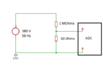
And whit this voltage divider? What do you think? There is a voltage of (380x50)/(50+1000) at the differential ADC input

Capture2.png
 

Re: ADC input: What are that resistance?

According to my math, the divider ratio is 20000:1, resulting in about 19 mV ADC input voltage.
 
Re: ADC input: What are that resistance?

Yes, that's good because the ADC has 16 bits and with that resolution there wouldn't be a lot of error.
 

Re: ADC input: What are that resistance?

You need to use the whole range of the ADC. If VDDA is 3.3 V, then you should accomodate the max input voltage to that voltage in order to use the full ADC range.
 
Re: ADC input: What are that resistance?

To measure mains AC voltages the MCU is probably earth-grounded or at least connected to neutral.
AC means the sine-wave goes negative and the TMS320F283xx A/D converter will not work with voltages below VSS_A even in differential-mode.
I don't see measurement of -ve voltages possible.

Yes but as a differential ADC it whill meassure the negative part as same like positive part. For example at 300V the adc's register will be FB35 and at -300V it will be FB35, so to other way I must know which it's the negative part. But I can measure it, I means the negative and positive cycle. It's correct?
 

Re: ADC input: What are that resistance?

From the TMS320xxx datasheet, I understand the MCU hardware for the A/D cannot read any voltage below ground, cannot read negative voltages with respect to common VSS_A. The Differential Input Model Fig. 5-3 does not show this, and with 50ohm it's a high-frequency model. They do not show the common-mode voltage.

Compare to a 3-phase energy metering IC like ADE7878A. This part's A/D can read AC voltage +/-0.5V to ground, operating off a single power supply, it is intended for mains measurements.
 
Status
Not open for further replies.

Similar threads

Part and Inventory Search

Welcome to EDABoard.com

Sponsor

Back
Top