Akshaydpal
Member level 1

hi,
i am working on pure sine wave inverter using pic 16f877A i have created a basic program for it.
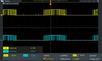
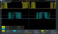
this is for 10khz switching. during simulation in proteus it is giving some pulses during off time as well . i dont know why it is giving that extra pulses.
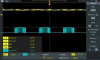
i had developed it on breadboard as well in DSO it is giving out similar pulses during off time.
images are attached kindly help me . im a newbi in this area.
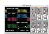
<a title="output2.JPG" href="http://obrazki.elektroda.pl/7319165600_1495789490.jpg"><img src="http://obrazki.elektroda.pl/7319165600_1495789490_thumb.jpg" alt="output2.JPG" /></a>
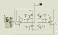
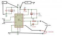
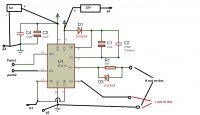
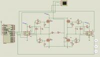
<a title="complete ckt.JPG" href="http://obrazki.elektroda.pl/4297777100_1495789540.jpg"><img src="http://obrazki.elektroda.pl/4297777100_1495789540_thumb.jpg" alt="complete ckt.JPG" /></a>
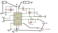
mosfet driver used is ir2110 and mosfet irf840n
this inverter ckt is not giving output in proteus simulation but i had shown the pwm output from pic and driver but when i tested those without mosfet on bread board pwm from pic was giving unwanted pulses during off time as shown in simulation output . and the driver output got me all confused the low side is boosted to 12 v but high side is approx 5-6 v. low side ias some how similar to pic pwm out put but not the high side it is like all time high .
power supply used is rectified and filtered ac from 220 v supply sepped down to 30 v and rectified with 3 different ckt for 5v , 5v and 12v.
- - - Updated - - -
<a title="TEK00003.PNG" href="http://obrazki.elektroda.pl/2497868300_1495792526.png"><img src="http://obrazki.elektroda.pl/2497868300_1495792526_thumb.jpg" alt="TEK00003.PNG" /></a>
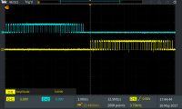
<a title="TEK00005.PNG" href="http://obrazki.elektroda.pl/6105827700_1495792578.png"><img src="http://obrazki.elektroda.pl/6105827700_1495792578_thumb.jpg" alt="TEK00005.PNG" /></a>
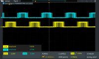
pwm output on dso
i am working on pure sine wave inverter using pic 16f877A i have created a basic program for it.
Code:
unsigned char x[51]={0,16,32,48,63,79,94,109,123,137,150,162,174,186,196,206,215,223,231,237,242,247,250,253,254,255,255,253,251,247,243,237,231,224,215,206,197,186,175,163,150,137,123,109,94,79,64,48,32,16,0};
void main()
{
unsigned char i;
TRISC.F2=0;
TRISC.F1=0;
PWM1_Init(5000);
PWM2_Init(5000);
PWM1_Start();
PWM2_Start();
while(1)
{
for(i=0;i<51;i++)
{
PORTC.F1=0;
PWM1_Set_Duty(x[i]);
}
for(i=0;i<51;i++)
{
PORTC.F2=0;
PWM2_Set_Duty(x[i]);
}

}
}i had developed it on breadboard as well in DSO it is giving out similar pulses during off time.
images are attached kindly help me . im a newbi in this area.

<a title="output2.JPG" href="http://obrazki.elektroda.pl/7319165600_1495789490.jpg"><img src="http://obrazki.elektroda.pl/7319165600_1495789490_thumb.jpg" alt="output2.JPG" /></a>

<a title="complete ckt.JPG" href="http://obrazki.elektroda.pl/4297777100_1495789540.jpg"><img src="http://obrazki.elektroda.pl/4297777100_1495789540_thumb.jpg" alt="complete ckt.JPG" /></a>
mosfet driver used is ir2110 and mosfet irf840n
this inverter ckt is not giving output in proteus simulation but i had shown the pwm output from pic and driver but when i tested those without mosfet on bread board pwm from pic was giving unwanted pulses during off time as shown in simulation output . and the driver output got me all confused the low side is boosted to 12 v but high side is approx 5-6 v. low side ias some how similar to pic pwm out put but not the high side it is like all time high .
power supply used is rectified and filtered ac from 220 v supply sepped down to 30 v and rectified with 3 different ckt for 5v , 5v and 12v.
- - - Updated - - -
<a title="TEK00003.PNG" href="http://obrazki.elektroda.pl/2497868300_1495792526.png"><img src="http://obrazki.elektroda.pl/2497868300_1495792526_thumb.jpg" alt="TEK00003.PNG" /></a>

<a title="TEK00005.PNG" href="http://obrazki.elektroda.pl/6105827700_1495792578.png"><img src="http://obrazki.elektroda.pl/6105827700_1495792578_thumb.jpg" alt="TEK00005.PNG" /></a>

pwm output on dso
Last edited by a moderator:

