Continue to Site

Welcome to EDAboard.com

Welcome to our site! EDAboard.com is an international Electronics Discussion Forum focused on EDA software, circuits, schematics, books, theory, papers, asic, pld, 8051, DSP, Network, RF, Analog Design, PCB, Service Manuals... and a whole lot more! To participate you need to register. Registration is free. Click here to register now.

About Variable Gain Amplifier Controlled by Microcontroller

Status
Not open for further replies.

reeraslan

Newbie level 4
Newbie level 4
Joined
May 21, 2012
Messages
6
Helped
1
Reputation
2
Reaction score
1
Trophy points
1,283
Activity points
1,357
I can properly amplify 40Khz ultrasonic signal using with mcp6022.
But later, I wanted to be able to amplify this signal with the gain in 4 different levels
This must be controlled by MCU
As the first picture, I thought I can switch the feedback resistors with MOSFETs. I fed the gate pin of BSS139 Mosfet with 1K on MCU pin
The idea of switching the MOSFET can change of Feedback resistor did not yield results.

1- Why is the solution in the picture not working properly when Mosfet is completely On ?
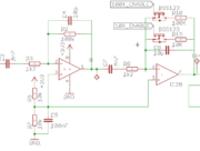


I will not use the digital potentiometer for cost reasons.I intend to implement the switching solution of resistors.
Here, I thought that analog switches or multiplexer , demultiplexers can be as a second method.

2- Can I use the 74h4051 IC as seen in the image for this question?


thanx
 
Last edited by a moderator:

Can you be more specific about what "not working" means. Scope capture or something?
How do you know the MOSFET is "completely on"? Your gate voltage has to be several volts higher than the source voltage, I doubt your MCU can put out that level.
You also need to think about that intrinsic diode in the MOSFET.

The problem with your second design (assuming you mean a 74HC4051) is that there's a significant on resistance of the mux that can vary widely. 70 ohms typical at 5V supply.
 
The first solution should normally work but I guess the internal diode-if it really exist-of the MOS disturbs the operation.You'd better perhaps use "low power switching act MOS" instead ??
 

Your attachments are too small to read.

Here's a non-inverting amplifier with gain controlled by analog switches such as the CD4066 or CD4051.
The advantage of this configuration is that the gain is basically insensitive to the switch on-resistance since only the small op amp input bias current goes through the switch resistance.
The number of switches and gain resistors can be expanded as needed, of course.
The resistor values shown give gains of 1, 2, and 4.

Capture.PNG
 
Last edited:
Note that the circuit in post #5 can be made inverting by grounding the op amp (+) input and connecting the signal to R2 in place of the ground connection.
That will reduce the gain by 1 for the given resistor values.
 

Depending on your voltage supply rails and microcontroller, you could also use a p-channel MMBFJ176 or MMBFJ177 instead of a CD4066 IC if you didn't need so many gain levels/switches. But these also still have Rds values which can influence the gain if not accounted for and there is variability among devices' Rds. If you only needed 1 switch and didn't want to use a whole chip I would use one of these. But as you need several I would recommend using the suggested 4066 as the tolerance of switch resistance within the same die is usually pretty good.
 

...........
I would recommend using the suggested 4066 as the tolerance of switch resistance within the same die is usually pretty good.
But even if the variation is low, the absolute switch resistance value still affects the gain.
That's why I like the circuit in post #5.
It is basically insensitive to the absolute value of the switch resistance.
 

Status
Not open for further replies.

Part and Inventory Search

Welcome to EDABoard.com

Sponsor

Back
Top