Continue to Site

Welcome to EDAboard.com

Welcome to our site! EDAboard.com is an international Electronics Discussion Forum focused on EDA software, circuits, schematics, books, theory, papers, asic, pld, 8051, DSP, Network, RF, Analog Design, PCB, Service Manuals... and a whole lot more! To participate you need to register. Registration is free. Click here to register now.

corporate feed dimensions

Status
Not open for further replies.

cehan

Junior Member level 2
Joined
Jun 2, 2013
Messages
21
Helped
0
Reputation
0
Reaction score
0
Trophy points
1,281
Activity points
1,428
hello
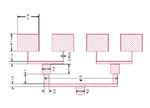
i am working on microstrip antenna array for first time...i have problem with designing corporate feed network for 4-patch array...
this problem is how to calculate the width w and length L of each section (z0=50 ohms) and for (z0=70.7 and 100 ohms) also the quarter wave transform.
for example in this figure antenna operate at 10 Ghz
how these dimensions are calculated as seen in this figure
بدون عنوان.png
 

hello
i am working on microstrip antenna array for first time...i have problem with designing corporate feed network for 4-patch array...
this problem is how to calculate the width w and length L of each section (z0=50 ohms) and for (z0=70.7 and 100 ohms) also the quarter wave transform.
for example in this figure antenna operate at 10 Ghz
how these dimensions are calculated as seen in this figure
View attachment 134338

Google "microstrip transmission line calculator" or get the free "txline" calculator from AWR. Rogers corp also has free transmission line calculator.
 

thanks edf for ur help.i know there is txline that can help..but i am looking for formula
that used to get w and l for corporate feed
 

There are a series of assumptions here. You are probably trying to create an array of four antennas to radiate in broadside. A corporate feed will have equal total length and a series of power dividers to distribute the input equally among the four antennas. Look into "T junction" dividers, you have three. You might also look into impedance converters (lambda/4 steps) to help connect everything. Mitered corners will probably also be helpful. Microwaves101 dot com is a good place to get help putting this together.

The impedance values you cite suggest a Wilkinson divider. If so that would add complexity to what you are trying to accomplish.
 
  • Like
Reactions: cehan

    cehan

    Points: 2
    Helpful Answer Positive Rating
There are a series of assumptions here. You are probably trying to create an array of four antennas to radiate in broadside. A corporate feed will have equal total length and a series of power dividers to distribute the input equally among the four antennas. Look into "T junction" dividers, you have three. You might also look into impedance converters (lambda/4 steps) to help connect everything. Mitered corners will probably also be helpful. Microwaves101 dot com is a good place to get help putting this together.

The impedance values you cite suggest a Wilkinson divider. If so that would add complexity to what you are trying to accomplish.

thanks Azulykit..i get all useful formula..but there is a small issue. when i am trying to design there are two condition z0 when w/h <1 or w/h>1...the question how i can investigate this while i dont have line width w while i have zo=50 ohmdesign-and-simulation-microstrip-patch-antenna-using-cst-microwave-studio-17-638.jpg
 

Patches typically have 130 Ohm impedance (or so) when fed at the edge. The cut-out you show can be used to gradually reduce the impedance to a lower value as you cut into the patch. Zo goes to 0 at the center. Other members have pointed you towards other impedance converters if the above expression is giving you trouble. It looks like you may have a formulation by Wheeler. Look up the reference and it should have the more complete description.
 

Status
Not open for further replies.

Part and Inventory Search

Welcome to EDABoard.com

Sponsor

Back
Top