Continue to Site

Welcome to EDAboard.com

Welcome to our site! EDAboard.com is an international Electronics Discussion Forum focused on EDA software, circuits, schematics, books, theory, papers, asic, pld, 8051, DSP, Network, RF, Analog Design, PCB, Service Manuals... and a whole lot more! To participate you need to register. Registration is free. Click here to register now.

[PIC] help me in doing an lcd program using pic16f877A

Status
Not open for further replies.

Girishs449

Newbie level 5
Newbie level 5
Joined
Dec 12, 2016
Messages
8
Helped
0
Reputation
0
Reaction score
0
Trophy points
1
Activity points
92
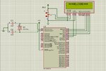
Hi, I'm new in pic microcontroller. can any one help me in this. i'm doing a program to display "welcome" in an LCD using pic16f877A. i've done it in proteus simulation and its working well. now i'm using a pic16f877 development board. i programmed the controller through pickit2. but its not working.
i'm using MPLAB ASM.
pic 16f877A.
is any error in my program?
can any one help please.
i've attached the simulation screenshot and the code. please help
Capture.JPG


Code ASM - [expand]
1
2
3
4
5
6
7
8
9
10
11
12
13
14
15
16
17
18
19
20
21
22
23
24
25
26
27
28
29
30
31
32
33
34
35
36
37
38
39
40
41
42
43
44
45
46
47
48
49
50
51
52
53
54
55
56
57
58
59
60
61
62
63
64
65
66
67
68
69
70
71
72
73
74
75
76
77
78
79
80
81
82
83
84
85
86
87
88
89
90
91
92
93
94
95
96
97
98
99
100
101
102
103
104
105
106
107
108
109
110
111
112
113
114
115
116
117
118
119
120
121
122
123
124
125
126
127
128
129
130
131
132
133
134
135
136
137
138
139
140
141
142
143
144
145
146
147
148
149
150
151
152
153
154
155
156
157
158
159
160
161
162
163
164
165
166
167
168
169
170
171
172
173
TITLE  "LCD4.ASM"               ; WORKING WITH AN LCD IN THE 4-BIT MODE
        LIST P=16F877A, R=DEC
        INCLUDE "P16F877A.INC"
 
        ; DATA SEGMENT
        CBLOCK 0X00C                   
        DEL, CMD                                ; VARIABLES FOR PASSING THE PARAMETERS
        TEMP, I                                 ; LOCAL VARIABLES
 
        ENDC
 
        ; CODE SEGMENT
        PAGE
        __CONFIG _CP_OFF  & _PWRTE_ON  & _WDT_OFF 
 
 
        ORG 0                           ; START PROGRAM AT THE BEGINNING OF MEM
        GOTO START
 
 
MSG0
        ADDWF   PCL, F
        DT" ***WELCOME***", 0
        
        
        START
        BSF     STATUS, RP0
        MOVLW   0X00 
        MOVWF   TRISB ^ 0X80
        MOVLW   0X7F
        MOVWF   OPTION_REG ^ 0X80
        BCF     STATUS, RP0
        CALL    INITLCD
        CLRF    I
 
 
L1      MOVF    I, W
        CALL    MSG0
        IORLW   0
        BTFSC   STATUS, Z       
        GOTO    L2
        CALL    WRITEDATA
        INCF    I, F
        GOTO    L1
 
L2
        GOTO    L2              ; ENDLESS LOOP
 
 
INITLCD 
        MOVLW   15
        MOVWF   DEL
        CALL    DELAY                   ; A 15 MSEC DELAY AFTER POWER IS ON
 
 
        MOVLW   3
        MOVWF   PORTB                   ; START LCD INIT PROCESS
        MOVLW   5
        MOVWF   DEL     
        CALL    DELAY                   ; WAIT FOR 5 MSEC       
 
 
        MOVLW   3
        MOVWF   PORTB                   ; START LCD INIT PROCESS
        BSF     PORTB, 4                ; TOGGLE THE LCD ENABLE PIN
        BCF     PORTB, 4
        MOVLW   5
        MOVWF   DEL     
        CALL    DELAY                   ; WAIT FOR 5 MSEC
 
 
        BSF     PORTB, 4                ; REPEAT THE RESET COMMAND (2ND TIME)
        BCF     PORTB, 4
        MOVLW   40                      ; WAIT FOR 200 USEC
        SUBLW   1
        SUBLW   0
        BTFSS   STATUS, Z
        GOTO    $-3
 
 
        BSF     PORTB, 4                ; REPEAT THE RESET COMMAND (3RD TIME)
        BCF     PORTB, 4
        MOVLW   40                      ; WAIT FOR 200 USEC
        SUBLW   1
        SUBLW   0
        BTFSS   STATUS, Z
        GOTO    $-3
 
 
        MOVLW   2                       ; INITIALIZE LCD 4-BIT MODE
        MOVWF   PORTB
        BSF     PORTB, 4                ; TOGGLE THE LCD ENABLE PIN
        BCF     PORTB, 4
 
 
        MOVLW   0X28                    ; 2-LINE MODE
        CALL    WRITECMD
 
 
        MOVLW   1
        CALL    WRITECMD                ; CLEAR DISPLAY
 
 
        MOVLW   5                       ; WAIT FOR 5 MSEC AFTER CLEARING
        MOVWF   DEL
        CALL    DELAY
 
 
        MOVLW   0X06                    ; CURSOR MOVE AFTER EACH CHAR
        CALL    WRITECMD
 
 
        MOVLW   0X0C                    ; TURN ON LCD AND ENABLE CURSOR
        CALL    WRITECMD
        RETURN
 
 
WRITECMD                                ; WRITE TO LCD A 1-BYTE COMMAND IN W
        MOVWF   TEMP
        SWAPF   TEMP, W
        ANDLW   0X0F                    ; LEAVE ONLY THE HIGH 4 BITS IN W
        MOVWF   PORTB
        BSF     PORTB, 4                ; TOGGLE THE E BIT
        BCF     PORTB, 4
        
        MOVFW   TEMP                    ; PROCEED WITH THE LOW BIT
        ANDLW   0X0F
        MOVWF   PORTB
        BSF     PORTB, 4                ; TOGGLE THE  BIT       
        BCF     PORTB, 4
 
 
        MOVLW   40                      ; WAIT FOR 200 USEC
        SUBLW   1
        SUBLW   0
        BTFSS   STATUS, Z
        GOTO    $-3
        RETURN
 
 
WRITEDATA                               ; WRITE TO LCD A 1-BYTE DATA IN W
        MOVWF   TEMP
        SWAPF   TEMP, W
        ANDLW   0X0F                    ; LEAVE ONLY THE LOWER 4 BITS IN W      
        MOVWF   PORTB
        BSF     PORTB, 5                ; SENDING DATA
        BSF     PORTB, 4                ; TOGGLE THE E BIT
        BCF     PORTB, 4
        
        MOVFW   TEMP                    ; PROCEED WITH THE LOW BIT
        ANDLW   0X0F
        MOVWF   PORTB
        BSF     PORTB, 5                ; SENDING DATA
        BSF     PORTB, 4                ; TOGGLE THE  BIT       
        BCF     PORTB, 4
        MOVLW   5                       ; WAIT FOR 5 MSEC
        MOVWF   DEL
        CALL    DELAY
        RETURN
 
DELAY
        MOVLW   200
        SUBLW   1                       ; THIS LOOP TAKES 5US*200 = 1MS
        SUBLW   0
        BTFSS   STATUS, Z
        GOTO    $-3
 
 
        DECFSZ  DEL,F
        GOTO    DELAY
        RETURN
        
        END

 
Last edited by a moderator:

I use normally a longer delay time before start the initialization. I checked the C lib I made and the delay is 120 ms. The init time varies for each type of LCD controller, so it's better to give a good tolerance. At the power up an 100 ms delay is not a problem. As you mentioned that you code worked in Proteus, I didn't checked the entire source... So I looked right where I had problems once.
 
Also try this CONFIG, ensure OSC selection.

__CONFIG _CP_OFF & _WDT_OFF & _BODEN_OFF & _PWRTE_ON & _XT_OSC & _WRT_OFF & _LVP_OFF & _CPD_OFF
 
but its not working
What exactly is or is not happening ? Anyway, are you sure the display used in the actual assembly is based on the same controller for which the above code was wrote ?

- - - Updated - - -

In addition, along with ysba's suggestion, I would also recommend you insert a short delay between both statements below:
Code:
BSF     PORTB, 4                ; TOGGLE THE LCD ENABLE PIN
BCF     PORTB, 4

Depending on the assembly arrangement you made for wirings, this significantly ensures a more steady signal level to the LCD.
 
thanks all.
yes lcd is working with same contoller with sample program get with the development board.
i'll do the corrections and try. hoping your valuable advices again

thanks all
 

hi friends. as per the advices i changed the code n its now working. there is another problem that i found is the oscillator freq. in proteus its only 1MHZ and in development board its 20MHZ. now the problem is solved. thanks all.


But i've another doubt.

In proteus i found that in properties of PIC we can change XTAL freq and the simulation speed also varies accordingly.
But then whats the significance of external XTAL??
even if i removed the external XTAL the simulation works well.

11.JPG

12.JPG

Can pic 16F877A works without external XTAL like pic 12F625??
 

even if i removed the external XTAL the simulation works well.
In your code above, it is not explicitly configured any clock source.
I would suppose internal RC oscillator as being default.
 
I'm doing Binary Decimal Hex converter with pic16F877A.
I've done almost 80%. I can display the data from the 4X4 matrix keypad. But the problem is i dont know how to move the keypad data to a single register. i mean that if we want the data 234 we can press 2 the 3 and 4 individually. we can save it on three registers. but how to get 234 in single register? how can the pic knows the first pressed key is 2, 2nd pressed is 3??
i attached the code of keypad section.

Code:
BEGIN
	CALL CHECK_KEYPAD
	GOTO BEGIN


CHECK_KEYPAD

	BSF PORTC, 0
	BTFSC PORTC, 4
CALL	SELECT_CHAR1
	BTFSC PORTC, 5
CALL	SELECT_CHAR4	
	BTFSC PORTC, 6
CALL	SELECT_CHAR7
	BTFSC PORTC, 7
CALL	SELECT_CHAR11
	BCF PORTC, 0
		
	BSF PORTC, 1

	BTFSC PORTC, 4
CALL	SELECT_CHAR2
	BTFSC PORTC, 5
CALL	SELECT_CHAR5	
	BTFSC PORTC, 6
CALL	SELECT_CHAR8
	BTFSC PORTC, 7
CALL	SELECT_CHAR10
	BCF PORTC, 1
	
	BSF PORTC, 2
	BTFSC PORTC, 4
CALL	SELECT_CHAR3
	BTFSC PORTC, 5
CALL	SELECT_CHAR6	
	BTFSC PORTC, 6
CALL	SELECT_CHAR9
	BTFSC PORTC, 7
CALL	SELECT_CHAR12
	BCF PORTC, 2
		
	BSF PORTC, 3
	BTFSC PORTC, 4
CALL	SELECT_CHAR13
	BTFSC PORTC, 5
CALL	SELECT_CHAR14
	BTFSC PORTC, 6
CALL	SELECT_CHAR15
	BTFSC PORTC, 7
CALL	SELECT_CHAR16
	BCF PORTC, 3
	BTFSC PORTD, 0
CALL	SELECT_CHAR20
	BTFSC PORTD, 1
CALL	SELECT_CHAR21
	RETURN
	
SELECT_CHAR20
	BTFSC	PORTD, 0	
	GOTO $-1
	MOVLW	0X10
	CALL 	WRITECMD
	MOVLW	15
	MOVWF	DEL
	CALL 	DELAY
RETURN
SELECT_CHAR21
	BTFSC	PORTD, 1	
	GOTO $-1
	MOVLW	0X14
	CALL 	WRITECMD
	MOVLW	15
	MOVWF	DEL
	CALL 	DELAY
RETURN
SELECT_CHAR1
	BTFSC	PORTC, 4	
	GOTO $-1
	MOVLW	"1"
	CALL 	WRITEDATA
RETURN
SELECT_CHAR2

	BTFSC	PORTC, 4	
	GOTO $-1
	MOVLW	"2"
	CALL 	WRITEDATA
RETURN
SELECT_CHAR3
	BTFSC	PORTC, 4	
	GOTO $-1
	MOVLW	"3"
	CALL 	WRITEDATA
RETURN
SELECT_CHAR4
	BTFSC	PORTC, 5	
	GOTO $-1
	MOVLW	"4"
	CALL 	WRITEDATA
RETURN
SELECT_CHAR5
	BTFSC	PORTC, 5	
	GOTO $-1
	MOVLW	"5"
	CALL 	WRITEDATA
RETURN
SELECT_CHAR6
	BTFSC	PORTC, 5	
	GOTO $-1
	MOVLW	"6"
	CALL 	WRITEDATA
RETURN
SELECT_CHAR7
	BTFSC	PORTC, 6	
	GOTO $-1
	MOVLW	"7"
	CALL 	WRITEDATA
RETURN
SELECT_CHAR8
	BTFSC	PORTC, 6	
	GOTO $-1
	MOVLW	"8"
	CALL 	WRITEDATA
RETURN
SELECT_CHAR9
	BTFSC	PORTC, 6	
	GOTO $-1
	MOVLW	"9"
	CALL 	WRITEDATA
RETURN
SELECT_CHAR10
	BTFSC	PORTC, 7
	GOTO $-1
	MOVLW	"0"
	CALL 	WRITEDATA
RETURN
SELECT_CHAR11
	BTFSC	PORTC, 7
	GOTO $-1
	MOVLW	"A"
	CALL 	WRITEDATA
RETURN
SELECT_CHAR12
	BTFSC	PORTC, 7
	GOTO $-1
	MOVLW	"B"
	CALL 	WRITEDATA
RETURN	
SELECT_CHAR13
	BTFSC	PORTC, 4
	GOTO $-1
	MOVLW	"C"
	CALL 	WRITEDATA
RETURN
SELECT_CHAR14
	BTFSC	PORTC, 5
	GOTO $-1
	MOVLW	"D"
	CALL 	WRITEDATA
RETURN
SELECT_CHAR15
	BTFSC	PORTC, 6
	GOTO $-1
	MOVLW	"E"
	CALL 	WRITEDATA
RETURN
SELECT_CHAR16
	BTFSC	PORTC, 7
	GOTO $-1
	MOVLW	"F"
	CALL 	WRITEDATA
RETURN
 

if we want the data 234 we can press 2 the 3 and 4 individually. we can save it on three registers. but how to get 234 in single register? how can the pic knows the first pressed key is 2, 2nd pressed is 3??

It depends on what you intend to do with that pressed sequence. If you want, for example, to resend via the serial or display it in LCD, then you really need to save the typed history in a 3-position array ( ie in a FIFO buffer for example ), but if you want to do only a local comparison, such as In a keylock for example, so in this case, considering that the above value is less than 255, it could be saved in just 1 byte.
 

Ok fine. but how to get the data to single register?

from my knowledge i prepare this. please tell an easiest way

press key 2 and move data to reg1
press key 5 and move data to reg2
press key 4 and move data to reg3

now new register reg4= 100*reg1 + 10* reg2 + reg3


is this the only way to get the individual data into single register as we pressed 2, 5, 4 individually
 

In assembly you can easily add cumulatively the previous result with the newcoming value:

  • press key 2 and move data to regx
regx ← ( 2 )

  • press key 5 and add data to regx
regx ← regx + 10 * ( 5 )

  • press key 4 and add data to regx
regx ← regx + 100 * ( 4 )

For the above value, you could not store value at 8-bit size register anymore.
 

Status
Not open for further replies.

Similar threads

Part and Inventory Search

Welcome to EDABoard.com

Sponsor

Back
Top