Continue to Site

Welcome to EDAboard.com

Welcome to our site! EDAboard.com is an international Electronics Discussion Forum focused on EDA software, circuits, schematics, books, theory, papers, asic, pld, 8051, DSP, Network, RF, Analog Design, PCB, Service Manuals... and a whole lot more! To participate you need to register. Registration is free. Click here to register now.

Stabilizer Design Help

Status
Not open for further replies.

Okada

Banned
Advanced Member level 4
Joined
Jun 16, 2016
Messages
1,159
Helped
129
Reputation
252
Reaction score
129
Trophy points
63
Activity points
0
I am designing a PIC18F46K22 based Stabilizer. I read about CVTs (Constant Voltage Transformers) and found that in that the secondary will be saturated and output is not pure sine wave but instead the peak will be flattened and hence I am trying to design my own stabilizer. Cost is not a problem. I want to make a good design.

These are my Transformer Calculations. Are these correct ? What will be the normal number of primary turns in a stabilizer transformer ? For calculation purposes I have assumed primary number of turns as 100. If this can be reduced to 50 then that is also fine.

110V to 290V

Vpri/Vsec = N

Npri/Nsec = N

Nsec = Npri/N

290V/230V = 1.26, Nsec = 100 / 1.26 = ~ 79

270V/230V = 1.174, Nsec = 100 / 1.174 = ~ 85

250V/230V = 1.087, Nsec = 100 / 1.087 = ~ 92

230V/230V = 1, Nsec = 100 / 1 = 108.7 = 100

210V/230V = 0.91, Nsec = 100 / 0.91 = ~ 110

190V/230V = 0.826, Nsec = 100 / 0.826 = ~ 121

170V/230V = 0.739, Nsec = 100 / 0.739 = ~ 135

150V/230V = 0.652, Nsec = 100 / 0.652 = ~ 153

130V/230V = 0.565, Nsec = 100 / 0.565 = ~ 177

110V/230V = 0.478, Nsec = 100 / 0.478 = ~ 209


Instead of other type switching methods I will just switch the correct tap to get constant 230V output. Number of Relays required is not a problem. I will be using

I will be using a board similar to this but with 10 Relays. I will use same Omron Relays used in this board. These will be a 20x4 LCD also.

https://www.sainsmart.com/omron-8-c...uino-mega2560-r3-uno-r3-raspberry-pi-arm.html


How to choose core for the transformer ?

- - - Updated - - -

Edit:

The tarnsformer min and max voltages will be

110/1.26 = 87V

290/0.478 = 607V

Is this 607V a normal voltage in a bulky transformer based stabilizer ? Can I get relays for these voltages. The relays will turn to NO position to provide 230V output. Relays with higher voltages at its input will be in NC position.
 

hi ,
using tap on transformer is old method , now days in industry we use toroidal autotransformers with servomotor. The servomotor is used to move the brush on the autotransformer , The action of the servomotor is controlled by a PI regulator
svc2000in.jpg
The regulator can be analog or digital . This works in 3 phase systems also, with separate autotransformer for each phase . I recently installed a 60 kVA stabiliser like that
 
Last edited:

Hi

I have seen servo stabilizers but read that they have geared motors and they are prone to wear-and-tear. Here they use multitapped transformer with relays.

I reduced the voltage range. These are my new calculations. Have to get the transformer wound for testing. According to my transformer the output varies between 206V to 230V.

170 to 180, N = 0.826, L = 170/0.783 = 217, M = 180/0.783 = 230, Nsec = 64 turns
181 to 200, N = 0.826, L = 181/0.87 = 206, M = 200/0.87 = 230, Nsec = 57 turns
201 to 220, N = 0.91, L = 201/0.957 = 210, M = 220/0.957 = 230 = 52 turns
221 to 240, N = 1.0, L = 221/1.0435 = 212, M = 240/1.0435 = 230 = 48 turns
241 to 260, N = 1.087, L = 241/1.13 = 213, M = 260/1.13 = 230 = 44 turns
261 to 280, N = 1.174, L = 261/1.217 = 215, M = 280/1.217 = 230 = 41 turns
281 to 290, N = 1.26, L = 281/0.79 = 223, M = 290/1.261 = 230 = 40

N is turns ratio.
L means least
M means most
 

These are my new calculations. Have to get the transformer wound for testing
Why don't you show what is exactly the issue in a simplest fashion ? If you just want that others check your design to certify if your assumptions are correct, instead of populating the thread with the whole result for each tap of the transformer, it wouldn't be better if you just show up the formulae/reference that you took so that others give you some additional advice to you consider in your design ?
 

The formula I have used is

N = turns ratio.

Vpri/Vsec = Npri/Nsec = N

I just want to know whether the turns calculations for different voltages are correct or not. I also want to know about what iron core to use and dimension of the core.
 

Your ratio calculations are correct.

But you cannot assume a primary number of turns, you require to calculate them based on the standard transformer EMF equation:

E = 4.44*f*a*N*B which you can algebraically re-arrange for number of turns.
where
E = applied RMS voltage (sinewave)
f = Frequency in Hertz
a = iron core cross sectional area (in m2)
N = number of turns
B = working flux density (Tesla)

For low cost magnetic steels, I would suggest no more than 1.2 Tesla at your MAXIMUM PRIMARY INPUT voltage.
 
  • Like
Reactions: Okada

    Okada

    Points: 2
    Helpful Answer Positive Rating
what is the frequency in your country ?
you can use E + I core for 50 HZ .
There is a simplified calculation used in practice : number of turns / volt = 50/A ; where A is the surface of transversal section of the core of the coil in mm^2.
Once you have turns/volt , primary is : turns/volt x primary voltage . Secondary is :turns/volt x secondary voltage
Example :
Given : primary = 220V ac, secondary 12Vac , 25 mmm^2 cross section area of core .
What are the turns for primary and secondary coils ?
turn/volt = 50/25 = 2
primary coil 2 x 220 = 440 turns , secondary coil 2 x 12 = 24 turns .

Usually you need to begin from the power of the transformer . You first calculate the power S you need in [VA] units .
Then the cross section area of the core is A = ~1.4 x sqrt (S) in [ cm^2] units ;
Then you get on with the turns/volt calculations and coil calculations .
You also need to get the cross section of the coil wire to support the current for the power (S) you need
 
Last edited:
  • Like
Reactions: Okada

    Okada

    Points: 2
    Helpful Answer Positive Rating
@schmitt rigger

Ok.

@zsolt1

F = 50 Hz

Ok. i will try to use both methods of calculation.
 

what is the frequency in your country ?
you can use E + I core for 50 HZ .
There is a simplified calculation used in practice : number of turns / volt = 50/A ; where A is the surface of transversal section of the core of the coil in cm^2.
Once you have turns/volt , primary is : turns/volt x primary voltage . Secondary is :turns/volt x secondary voltage
Example :
Given : primary = 220V ac, secondary 12Vac , 25 cm^2 cross section area of core .
What are the turns for primary and secondary coils ?
turn/volt = 50/25 = 2
primary coil 2 x 220 = 440 turns , secondary coil 2 x 12 = 24 turns .

Usually you need to begin from the power of the transformer . You first calculate the power S you need in [VA] units .
Then the cross section area of the core is A = ~1.4 x sqrt (S) in [ cm^2] units ;
Then you get on with the turns/volt calculations and coil calculations .
You also need to get the cross section of the coil wire to support the current for the power (S) you need.
For the example above : lets say we need only 100 VA power. So primary curent : 100VA/220V = 0.45 A, secondary curent : 100VA/12V=8.3 A.
So (simplified calculus, only for small transformers like this) primary coil wire diameter= 0.8 x sqrt(primary current) [mm]
secondary coil wire diameter=0.8 x sqrt (secondary current) [mm]
When calculating the coil, you also need to consider if the space required by the coil fits the window you have on the core .
This simplified calculations are used in practice for small transformers . For more bigger transformers where efficiency is an issue , you use formula like described by Schmitt trigger , that type of calculus is iterative because after each step you have to do checks which can bring you back to previous steps . (current density check, over temperature check , mechanical - electrical rigidity check - some transformers are immersed in oil to improve isolation and help cooling , this is in the kVA & MVA range so don't bother )

- - - Updated - - -

what is the frequency in your country ?
you can use E + I core for 50 HZ .
There is a simplified calculation used in practice : number of turns / volt = 50/A ; where A is the surface of transversal section of the core of the coil in mm^2.
Once you have turns/volt , primary is : turns/volt x primary voltage . Secondary is :turns/volt x secondary voltage
Example :
Given : primary = 220V ac, secondary 12Vac , 25 mmm^2 cross section area of core .
What are the turns for primary and secondary coils ?
turn/volt = 50/25 = 2
primary coil 2 x 220 = 440 turns , secondary coil 2 x 12 = 24 turns .

Usually you need to begin from the power of the transformer . You first calculate the power S you need in [VA] units .
Then the cross section area of the core is A = ~1.4 x sqrt (S) in [ cm^2] units ;
Then you get on with the turns/volt calculations and coil calculations .
You also need to get the cross section of the coil wire to support the current for the power (S) you need

units are wrong in the above quoted post , cross section of core is in cm ^2 not mm^2 :grin:
 
Last edited:
  • Like
Reactions: Okada

    Okada

    Points: 2
    Helpful Answer Positive Rating
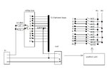
Similar to stella 300-1 , i would try this
stab.jpg

The input voltage is 220 V and rel6 is active . If the voltage falls lets say to 200 V , you need to go to to tap 8 . You do this in the following steps:
1. rel 6 active, rel7 active
2. rel 6 not active , rel 7 active,
3. rel 7 active , rel 8 active
4. rel 7 not active , rel 8 active.

For one short moment the 10 ohm resistence shorts two consecutive taps. Since voltage drop is only 5 V , the short transition between taps does not affect anything , and the supplied receiver is not seeing the commutations.
In the Stella300 stabiliser the commutator was mechanically so built that the cursor was leaving previous tap only when it already reached next tap .This ensured no interruption

PS: for tap 6 as reference, upper taps are above 220 , lower taps are below 220
 
Last edited:

@ zsolt1

I received Invalid attachment message for attachment in post #11.

I am designing Automatic Stabilizer. One for a Client and one for myself. Transformer is for personal use stabilizer.
 

Ok. Logging in again worked. Can you provide the transformer specification (full details). I have to get the transformer manufactured.
 

I don't have it anymore , It was 300 VA rated.
We can calculate your autotransformer together . Do you know the power you need ?
You need to add together the appliances you want to supply .
If they are in [W] , k[W] , you can use a ~ 0.8 power factor to get the [VA] . Than the transformer will need to be at least 1.5 times bigger than that power .
The 5 V steps are good i think , you can take a few below and above 220 V . (usually voltage should not vary more than +- 15 % of nominal voltage specified by contract with supplier )
 

The design shown in post #11 is good in terms of stabilised output with very little variation (5V). Thus this particular design is capable to handle an input range from 195V to 245V employing a large number of relays. This design will not work where the fluctuation of supply is beyond this range.

I have designed one stabiliser using 3 relays. Data of the stabiliser is as follows.

Input range - 121V to 275V
Output - 210V to 240V.
Number of taping - 4
Number of relay for AVR function - 3.
Taping on corresponding voltage - 0V, 158V, 210V, 240V, 275V.
I have practically tested the Stabiliser.
 

I am seriously doubting of the effectiveness of such a system with that drop between gaps. If the goal is to make the output really "stable" in a distribution grid so unreliable it would be better to start thinking about a double conversion inverter system. I would not be surprised to see a ceaseless switching between taps near to the threashold.
 

Ok. Let me do the tarnsformer calculations first. I think refrigirator wattage is 150W. Lets take maqx wattage as 300W. I need three stabilizers for personal use. One for refrigirator, one for Washing machine and one for Dish Washer. All 3 are inductive loads.

So, lets assume pf as 0.8.

So, P(VA) = 300 * 0.8 = 240VA.

So, 300VA or 500VA is enough for my purpose.

300W load corresponds to 375VA
 

Yes, you are right. I made a mistake in the calculation. it is

P(VA) = P(W) / PF = 300 / 08 = 375VA.
 

Status
Not open for further replies.

Similar threads

Part and Inventory Search

Welcome to EDABoard.com

Sponsor

Back
Top