T
treez
Guest

Hello,
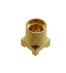
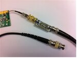
We are scoping the output voltage of a 100W (1V5, 65A output) , 3MHz Vicor VTM48’ power module with a Scope Probe PCB Adapter (as in attached JPEG) soldered into the PCB. This is essential since the 3MHz VTM48 module cannot be scoped with the scope probe with its ground 'tail' clip, -because there’s too much noise like that.
However, even when using this probe PCB adapter, the result is inaccurate, and there is more ripple shown on the scope than actually exists…..a good percentage of the ripple is coupling into the scope probe lead. –We know this because when you touch the scope tip to some ground net copper, and also connect the scope GND barrel to the same GND net via a little bit of stiff wire, you can then see all the “Pickup”. The “pickup” has an amplitude about half that of the ripple amplitude seen when the output voltage is scoped with the scope probe PCB adapter.
Therefore, half of the ripple seen when scoping the output is just “pickup”.
As you know, its important to assess the degree of ‘pickup’ by probing with the scope tip and barrel both connected to the same GND net. As such, why is it not common to see the Scope Probe PCB adapters soldered into PCB’s such that the entire adapter metal is connected to the same GND net….then its easy for people to just shove the scope probe into the adapter and look at the amount of “pickup”.
So why is this rarely done?


