Continue to Site

Welcome to EDAboard.com

Welcome to our site! EDAboard.com is an international Electronics Discussion Forum focused on EDA software, circuits, schematics, books, theory, papers, asic, pld, 8051, DSP, Network, RF, Analog Design, PCB, Service Manuals... and a whole lot more! To participate you need to register. Registration is free. Click here to register now.

[SOLVED] Phase of a reflected signal depending on a load impedance: 0 or 180 degree?

Status
Not open for further replies.

CHL

Member level 3
Member level 3
Joined
Jan 20, 2015
Messages
60
Helped
2
Reputation
4
Reaction score
2
Trophy points
8
Visit site
Activity points
550
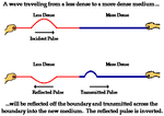
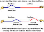
u10l3a6.gifu10l3a7.gif
(https://www.physicsclassroom.com/class/waves/Lesson-3/Boundary-Behavior)

Hello

As you can see above, when a wave meets a different impedance, it is reflected.

If the load impedance is higher, the phase is inverted, but if the load impedance is lower, the phase is not inverted.

However, according to the reflection coefficient equation,

(ZL-Z0)/(ZL+Z0)

when the ZL is higher, the phase should not be inverted. Also when the ZL is smaller, the phase should be inverted.

This is a totally opposite way

What is wrong with these??
 

I always thought that reflection causes a phase inversion but transmission does not. I did not know that it depends on the sign of the impedance difference or mismatch. A very similar thing happens on optics but the wave penetrates into the other medium before getting reflected. I need to see the real mechanism of the reflection process...

- - - Updated - - -

I read the link supplied: physicsclassroom but I could not understand because no explanations were given...
 

If the load impedance is higher, the phase is inverted, but if the load impedance is lower, the phase is not inverted.

Don't agree with your interpretation of the mechanical wave setup. I would associate less dense medium on the right to ZL > Z0, so it confirms the reflection coefficient formula.

Generally, there's no unequivocal assignment of electrical equivalent circuits to mechanical, acoustical, thermal, whatsoever problems. So may be you have a different correspondence in mind.
 
  • Like
Reactions: CHL

    CHL

    Points: 2
    Helpful Answer Positive Rating
Take into account that signs can be different if you consider voltages or currents.

At the load, we have the combination of incident and reflected waves following this convention:

VL = VINC + VREF
IL = IINC - IREF

ZL = VL / IL
Γ = VREF / VINC

Let's see the boundary conditions at the load in the two extreme cases:

If the load is a short circuit: V=0, so it must be VREF=-VINC, and current is maximum: IINC=-IREF , so IL=2*IINC

If the load is an open circuit: I=0, so it must be IREF=IINC, and voltage is maximum: VINC=VREF , so VL=2*VINC

You can check that these conditions agree with

Γ = VREF/VINC = (ZL-Z0)/(ZL+Z0)

We could adopt the other convention changing the sign of IREF, but the results are the same.

If in your analogy you associate voltage V with vertical displacement Y, the boundary condition at the load is Y=0, i.e. ZL=0 in the analogy and the voltage wave is inverted.
 
If the load is a short circuit: V=0, so it must be VREF=-VINC, and current is maximum: IINC=-IREF , so IL=2*IINC

If the load is an open circuit: I=0, so it must be IREF=IINC, and voltage is maximum: VINC=VREF , so VL=2*VINC

.

I always wondered why reflection from metals and glasses are different; you have explained nicely...
 

Status
Not open for further replies.

Part and Inventory Search

Welcome to EDABoard.com

Sponsor

Back
Top