pravin b
Member level 5

- Joined
- May 20, 2012
- Messages
- 85
- Helped
- 2
- Reputation
- 4
- Reaction score
- 1
- Trophy points
- 1,288
- Location
- Mumbai, India
- Activity points
- 2,083
Hello Friends,
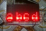
I am trying to interface the p10 led matrix display module with pic16f1939 running at 32MHz internal clock, MPLABx & HI TECH C Compiler.
To send the data to display I am using software spi routine (attached below). and regarding the protocol details I am referring DMD Notes.txt found here
. Since "i think" i am doing same as specified in the txt file, however I dont see anything on my display, its just blank. It would be nice if someone can help me. I have written a code to display "abcd" on the display through 16*4 array.
my main code
my spi routine
pin assignment
Thanks!
I am trying to interface the p10 led matrix display module with pic16f1939 running at 32MHz internal clock, MPLABx & HI TECH C Compiler.
To send the data to display I am using software spi routine (attached below). and regarding the protocol details I am referring DMD Notes.txt found here
HTML:
http://forum.freetronics.com/viewtopic.php?t=5754my main code
Code:
#include <htc.h>
#include "include.h"

// PIC16F1939 Configuration Bit Settings
__CONFIG(FOSC_INTOSC & WDTE_OFF & PWRTE_ON & MCLRE_ON & CP_OFF & CPD_OFF & BOREN_OFF & CLKOUTEN_OFF & IESO_OFF & FCMEN_OFF);
__CONFIG(WRT_OFF & VCAPEN_OFF & PLLEN_ON & STVREN_ON & BORV_LO & LVP_OFF);

//                                a    b    c    d
unsigned char dmdbuff[16][4]={//C0    C1   C2   C3
                                {0x00,0x00,0x00,0x00},  //R0
                                {0x00,0x00,0x00,0x00},  //R1
                                {0x00,0x00,0x00,0x00},  //R2
                                {0x00,0x00,0x00,0x00},  //R3
                                {0x00,0x00,0x00,0x00},  //R4
                                {0x00,0x00,0x00,0x00},  //R5
                                {0x00,0x00,0x00,0x00},  //R6
                                {0x00,0x00,0x00,0x00},  //R7
                                {0x00,0x20,0x00,0x04},  //R8
                                {0x38,0x20,0x38,0x04},  //R9
                                {0x44,0x2c,0x44,0x34},  //R10
                                {0x04,0x32,0x40,0x4c},  //R11
                                {0x3c,0x22,0x40,0x44},  //R12
                                {0x44,0x32,0x40,0x44},  //R13
                                {0x44,0x32,0x44,0x4c},  //R14
                                {0x38,0x2c,0x38,0x34},  //R15
                            };

char row,x,y;
void main()
{
    system_init();
    while(1)
    {
        show_row(0);
        show_row(1);
        show_row(2);
        show_row(3);
    }
}


void system_init()
{
    OSCCON  = 0b01110000;   // 32 MHz Fosc w/ PLLEN_ON (config bit)
    TRISC=0b00000000;
//    PORTC=0;
    TRISD0=0;
    pin=0;
//    USART_Init();
//    ms1_delay(100);
//    USART_putstring("UART_OK\r");
    swspi_init();
}

void show_row(char temp)
{
    for(y=0;y<=3;y++)
    {
        swspi_write_byte(dmdbuff[(16-4)+temp][y]);
        swspi_write_byte(dmdbuff[(16-8)+temp][y]);
        swspi_write_byte(dmdbuff[(16-12)+temp][y]);
        swspi_write_byte(dmdbuff[(16-16)+temp][y]);
    }

    P10_LATCH=1;
    us500_delay(1);
    P10_LATCH=0;

    scan_row(temp);

    DISP_EN=0;
}

void scan_row(char temp)
{
    switch(temp)
    {
        case 0: P10_A=0;
                P10_B=0;
            break;
        case 1: P10_A=1;
                P10_B=0;
            break;
        case 2: P10_A=0;
                P10_B=1;
            break;
        case 3: P10_A=1;
                P10_B=1;
            break;
        default:P10_A=0;
                P10_B=0;
            break;
    }
}

void ms1_delay(unsigned int c)
{
    unsigned int i,j;
    for(i=1;i<=c;i++)
        for(j=0;j<=568;j++);
}

void us500_delay(unsigned int c)
{
    unsigned int i,j;
    for(i=1;i<=c;i++)
        for(j=0;j<=284;j++);
}

void interrupt my_ISR()
{
    if(RCIF)
    {
        USARTdataready=1;
        rx_byte=RCREG;
        if(FERR || OERR)
            CREN=0;
        USART_putchar(rx_byte);
        RCIF=0;
        get_data();
    }
}
my spi routine
Code:
void swspi_init( void )
{
    P10_A=0;
    P10_B=0;
    P10_PWM=0;
    P10_SCK=0;
    DISP_EN=1;
    P10_DATA=0;
    P10_LATCH=0;
}

/*************************************
write value to register
**************************************/
void swspi_write_byte(unsigned int temp)
{
	unsigned char n=8;
//    DISP_EN = 0;

//	temp |= 0x80;

//  	P10_SCK = 0;
  	while(n--)
   	{
        P10_SCK = 0;
     	if(temp&0x80)
      		P10_DATA=1;
     	else
      		P10_DATA=0;

        P10_SCK = 1;
        temp <<= 1;
   	}
	NOP();
//	DISP_EN = 1;
}
pin assignment
Code:
#define  P10_A    	RC0
#define  P10_B    	RC1
#define  P10_PWM	RC2
#define  P10_SCK	RC3
#define  DISP_EN    RC4
#define  P10_DATA   RC5
#define  P10_LATCH	RC6
Thanks!


