DigitalDeath
Junior Member level 1

Hello everyone,
This AD5142 IC has me stumped. I have tried every combination I can come up with and there is nothing I can do to make it work.
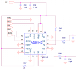
Here's the schematic:
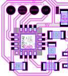
Here's the actual layout with the programming probe pads with the corresponding microcontroller controller terminals:
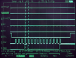
Here are the signals being sent for writting a 1 to pot 0:
I have tried floating -INDEP, connecting to to ground and to +5V. I have tried all 4 modes of SPI_MODE0 to SPI_MODE3
Here's a sample of a simple program I've tried:
This code on SPI mode 0 works perfectly fine on an AD5204 that used raising edge clock from the same family.
Here's a link to the 5142 Datasheet.
And here's the pinout:
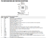
When turned on the wiper starts in the middle of the pot range as expected by default from factory but I can't get it to respond in any way.
I made a circuit with only the IC and no luck, I even soldered small wires to each pin to the IC by itself to make sure the connections were correct but no luck.
I tried the code with another IC from the same family and it worked perfectly fine.
This code on SPI mode 0 works fine on an AD5204 that uses raising edge clock from the same family.
I know it'll be some tiny little detail I forgot or missed that will make it work but I'm stumped right now.
Any help will be appreciated.
This AD5142 IC has me stumped. I have tried every combination I can come up with and there is nothing I can do to make it work.
Here's the schematic:

Here's the actual layout with the programming probe pads with the corresponding microcontroller controller terminals:

Here are the signals being sent for writting a 1 to pot 0:

I have tried floating -INDEP, connecting to to ground and to +5V. I have tried all 4 modes of SPI_MODE0 to SPI_MODE3
Here's a sample of a simple program I've tried:
Code:
#include <SPI.h>
void setup() {

  // pin 10 is the slave select for the digital pot
  pinMode( SS, OUTPUT); // set the slaveSelectPin as an output
  digitalWrite(SS, HIGH); // take the SS pin high to de-select the chip

  // MISO input needs to be ;ulled up for the AD5142
  pinMode( MISO, INPUT_PULLUP);

  SPI.begin();  // initialize SPI

  // set SPI speed to 500 kHertz, MSB, NORMAL LOW CLK and FALLING EDGE
  SPI.beginTransaction (SPISettings (500000, MSBFIRST, SPI_MODE1));

  // make sure the control register is correct:
  digitalWrite(SS, LOW);// take the SS pin low to select the chip
  SPI.transfer(0b11010000); // Copy serial register data to control register command 16
  SPI.transfer(0b00000011); // D2= 0 = potentiometer mode, D1=1 = enables EEPROM programing, D0=1 = allow update of wiper position
  digitalWrite(SS, HIGH); // take the SS pin high to de-select the chip

}

void loop() {
  writeOne();
  delay(10);
}

void writeOne(){

  digitalWrite(SS, LOW);// take the SS pin low to select the chip

  SPI.transfer(0b00010000); // command 1= set pot, pot selected= 0
  SPI.transfer(0b00000001); // pot value= 1

  digitalWrite(SS, HIGH); // take the SS pin high to de-select the chip

}
This code on SPI mode 0 works perfectly fine on an AD5204 that used raising edge clock from the same family.
Here's a link to the 5142 Datasheet.
And here's the pinout:

When turned on the wiper starts in the middle of the pot range as expected by default from factory but I can't get it to respond in any way.
I made a circuit with only the IC and no luck, I even soldered small wires to each pin to the IC by itself to make sure the connections were correct but no luck.
I tried the code with another IC from the same family and it worked perfectly fine.
This code on SPI mode 0 works fine on an AD5204 that uses raising edge clock from the same family.
I know it'll be some tiny little detail I forgot or missed that will make it work but I'm stumped right now.
Any help will be appreciated.

