Continue to Site

Welcome to EDAboard.com

Welcome to our site! EDAboard.com is an international Electronics Discussion Forum focused on EDA software, circuits, schematics, books, theory, papers, asic, pld, 8051, DSP, Network, RF, Analog Design, PCB, Service Manuals... and a whole lot more! To participate you need to register. Registration is free. Click here to register now.

Low voltage, high current Buck conversion (Bucks in parallel)

Status
Not open for further replies.
T

treez

Guest
Newbie level 1
Our vin=28v
Vout is 1.5V and needs to be 160 Amps.
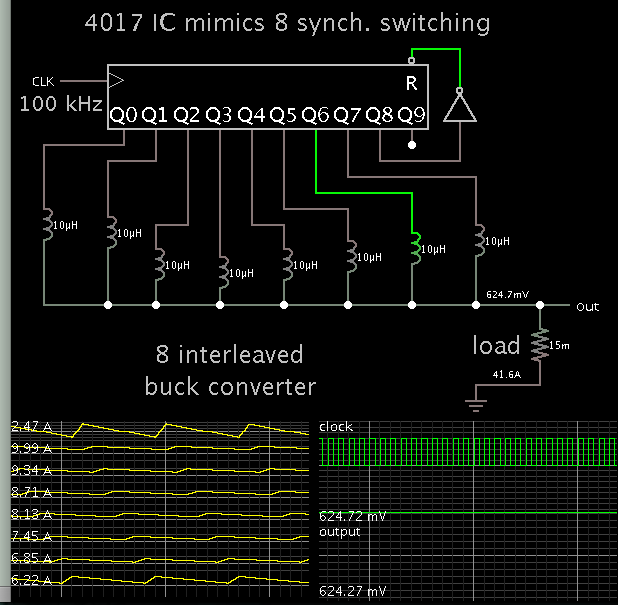
So we need to parallel many buck converters.
Regarding the buck controllers, do you prefer the 1_master/many_slave approach, or instead multi-master, whereby you are tying the transconductance error amplifiers of the separate controllers together?
..And why?
Master slave approach is like pg 24 of the LT3790 datasheet... (but that shows only 1 master 1 slave...we need many "slaves".

LT3790 datasheet:
http://cds.linear.com/docs/en/datasheet/3790fa.pdf
 

From seeing what happens in a simple simulation I've been running, it implies you should sense current independently in each of your 8 buck converters, so that you can turn that converter off as its current flow reaches zero, so that current cannot start to travel in the wrong direction through an inductor.

The 4017 IC fills in for 8 'robotic' synchronous switching systems. (Please ignore the difference in volt levels from your project.)

The scope trace shows that one of the inductors has lost its 'sync'. It is forced to pass current in the wrong direction. It is subtracting from the output stage, not adding to it. (This condition was also brought up in a recent thread about current sensing in buck converters. It had to do with the presence of a battery in the output stage.)


I post this in case it has anything to do with what approach you decide to take. Asynchronous (diode) switching does the job automatically but I recall one of your schematics showed you plan synchronous switching.
 
  • Like
Reactions: treez

    T

    Points: 2
    Helpful Answer Positive Rating
OK thanks...

Hello,
So, we are doing sixteen 10A Current mode bucks in parallel, all feeding into the same 1V5 output (vin=28v). Each of the 16 buck controllers (LTC3892) has an internal transconductance error amplifier, and we will tie all the outputs of these together….so that we get decent current sharing from buck to buck.
(however, there is actually no need for us to put all the bucks in parallel, because the load is in fact 16 separate processors, but it is said that due to PCB layout problems of having 16 separate 1V5 nodes, it is “easier” to have all 16 bucks feeing into one big 1V5 node supplying 80 Amps to the 16 processors)
We obviously only need one output divider, and then to connect it to all of the 16 buck controllers (the VFB pins) …however, that means a lot of interconnections, and it’s in fact easier on the PCB layout if we have 16 separate output dividers…one for each controller, and local to each controller.
The problem as you know is that due to the situation of large ground currents, and switching currents in the ground copper, that the “ground” at each LTC3892 controller will not be exactly the “same”. As you know, this can result in “ticking” and irregular behaviour.
Do you agree however, that the best way by far would be to have each buck supplying a separate 1V5 output? (instead of all feeding into one big 1v5, 160A output)?
The problem with 16 bucks in parallel, (all feeding into the same single output) and done by simply connecting together the transconductance error amplifier outputs of each of the controllers, is that of the potential for switching currents in the control grounds……You see, with one buck converter feeding into one output, all the necessary connections can be ‘star-grounded’ to a single star point, and all is well…no switching power currents can flow along lengths of control ground traces…..however, when you have 16 buck controllers, you then have 16 separate star points….and each star point obviously has to be connected to the others. So how on earth do you prevent switching power currents from flowing along the star point interconnections and creating ground bounce between the separate star points?...well the answer as you know, is to make the layout perfectly symetrical, but that is a big ask on a tight board.
This is why most parallel SMPS’s feeding into a single output either use those current sharing chips….which make an individual correction to the error amplifiers of each individual SMPS, such that they all pretty much share current.
So why is it that not one single semiconductor company shows multiple of their chips being used in parallel smps’s by simply connecting together the transconductance error amplifier outputs?

ltspice sim of just 8 bucks in pllel is attached.

LTC3892 sync buck controller wth internal transconductance error amplifier
https://www.linear.com/product/LTC3892
 

Attachments

  • Parallel Bucks.txt
    54.3 KB · Views: 83
Last edited by a moderator:

why you did not use multiphase power supply system?
 
  • Like
Reactions: treez

    T

    Points: 2
    Helpful Answer Positive Rating
Status
Not open for further replies.

Similar threads

Part and Inventory Search

Welcome to EDABoard.com

Sponsor

Back
Top