Terminator3
Advanced Member level 3

Article:
https://www.adv-radio-sci.net/4/21/2006/ars-4-21-2006.pdf
Frequency tuning is realized by adding varactor loading to matching circuit line. As i understand it works as varactor loaded line phase shifter. I can't understand meaning of this phrase:
As i understand λ/4 stub works as narrow-band short-circuit for varactor at RF. What is the meaning of "keep the biasing effort moderate"?
Also, in some designs there is no any RF grounding at all! For example:

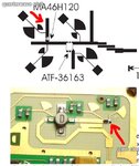
1) upper image represents VCO from article ars-4-21-2006.pdf with quarterwave "virtual ground" stub.
2) lower image represents another VCO, where varactor does not have any "virtual ground" quarterwave stub, only DC biasing.
I tried to use smith chart and can't understand how the second schematic is working, because series capacitance (varactor) can't transform open-circuited impedance (Г=1, a=0 deg) on smith chart, and parallel capacitance to ground is required. So adding quarterwave makes sense (Г=1, phi = 180deg) and impedance can be transformed using varactor capacitance to some point for frequency tuning.
https://www.adv-radio-sci.net/4/21/2006/ars-4-21-2006.pdf
Frequency tuning is realized by adding varactor loading to matching circuit line. As i understand it works as varactor loaded line phase shifter. I can't understand meaning of this phrase:
In both designs
the varactor diode is connected to a virtual ground provided
by a λ/4 transformation in order to keep the biasing effort
moderate.
As i understand λ/4 stub works as narrow-band short-circuit for varactor at RF. What is the meaning of "keep the biasing effort moderate"?
Also, in some designs there is no any RF grounding at all! For example:

1) upper image represents VCO from article ars-4-21-2006.pdf with quarterwave "virtual ground" stub.
2) lower image represents another VCO, where varactor does not have any "virtual ground" quarterwave stub, only DC biasing.
I tried to use smith chart and can't understand how the second schematic is working, because series capacitance (varactor) can't transform open-circuited impedance (Г=1, a=0 deg) on smith chart, and parallel capacitance to ground is required. So adding quarterwave makes sense (Г=1, phi = 180deg) and impedance can be transformed using varactor capacitance to some point for frequency tuning.


