masterx81
Member level 1

Hi!
I've "repaired" a chinese TIG welder (repair is a big word, only had cold solders, loose fastons, loose screws that must handle 200a, etc. Nothing burnt) and i'm studying the circuits for try to improve them.
I have a basic understanding of swtiching technologies (i know how they work and with some limits i can repair them), but i not know every aspect. I've learned on the net how a mosfet must be driven, the Qg curve, conduction and switching power loses, etc, but would be great to have some advice... I use this welder as a "learning bench" as have quite simple circuits (i've followed the tracks and i have all the schematics of the whole circuits :bang::shock::-D), and as far i can understand, it's not much optimized.
I've started to analyze the inverter, it have an H bridge composed of 3 paralleled n-channel mofets (23N50E - **broken link removed**, every of them have a 68ohm gate resistor) per branch, the output of the H bridge goes to 3 power transformers (via 3 4,7uF capacitors).
The chip controlling the the bridge (via an isolation transformer) is a KA3525A, the calculated switching frequency is 115khz (c=1nF, R=6.2k).
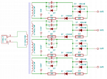
This is the schematic of the driver:
Gate driver
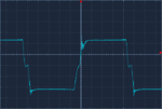
And this is the output (at the gate, after the 68 ohm gate, DC trace source-gate):
Low side
High side
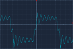
1uS/div, 5v/div for both, near 30vpp, the actual switching frequency is 103.1khz
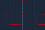
This is how the isolation transformer is driven (24v supply, with h bridge at the output of the 3525):
Transformer input
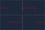
1uS/div, 10v/div, 50vpp
The first thing that i notice is that bad oscillation on the high side (why is present on the high side but not on the low side? Error itroduced by oscilloscope?), second one is the little ringing also on the low side, third one is that the gate is driven at much less the 10v reccomended for complete gate closing,
I've still not calculated the correct gate charge/switching power losess (first i've had the need to measure what was the voltage swing on the gate)
So, to my limited understanding, i would say that is better to create a new gate driver that reach at least the 10v gate charge, eliminate that oscillation on high side and check the switching losess to see if there is enough gate charge...
Can someone please help me, and tell me if i'm going in the wrong direction?
Really thanks, any help is much appreciated :-D
I've "repaired" a chinese TIG welder (repair is a big word, only had cold solders, loose fastons, loose screws that must handle 200a, etc. Nothing burnt) and i'm studying the circuits for try to improve them.
I have a basic understanding of swtiching technologies (i know how they work and with some limits i can repair them), but i not know every aspect. I've learned on the net how a mosfet must be driven, the Qg curve, conduction and switching power loses, etc, but would be great to have some advice... I use this welder as a "learning bench" as have quite simple circuits (i've followed the tracks and i have all the schematics of the whole circuits :bang::shock::-D), and as far i can understand, it's not much optimized.
I've started to analyze the inverter, it have an H bridge composed of 3 paralleled n-channel mofets (23N50E - **broken link removed**, every of them have a 68ohm gate resistor) per branch, the output of the H bridge goes to 3 power transformers (via 3 4,7uF capacitors).
The chip controlling the the bridge (via an isolation transformer) is a KA3525A, the calculated switching frequency is 115khz (c=1nF, R=6.2k).
This is the schematic of the driver:
Gate driver

And this is the output (at the gate, after the 68 ohm gate, DC trace source-gate):
Low side

High side

1uS/div, 5v/div for both, near 30vpp, the actual switching frequency is 103.1khz
This is how the isolation transformer is driven (24v supply, with h bridge at the output of the 3525):
Transformer input

1uS/div, 10v/div, 50vpp
The first thing that i notice is that bad oscillation on the high side (why is present on the high side but not on the low side? Error itroduced by oscilloscope?), second one is the little ringing also on the low side, third one is that the gate is driven at much less the 10v reccomended for complete gate closing,
I've still not calculated the correct gate charge/switching power losess (first i've had the need to measure what was the voltage swing on the gate)
So, to my limited understanding, i would say that is better to create a new gate driver that reach at least the 10v gate charge, eliminate that oscillation on high side and check the switching losess to see if there is enough gate charge...
Can someone please help me, and tell me if i'm going in the wrong direction?
Really thanks, any help is much appreciated :-D


