Continue to Site

Welcome to EDAboard.com

Welcome to our site! EDAboard.com is an international Electronics Discussion Forum focused on EDA software, circuits, schematics, books, theory, papers, asic, pld, 8051, DSP, Network, RF, Analog Design, PCB, Service Manuals... and a whole lot more! To participate you need to register. Registration is free. Click here to register now.

[SOLVED] AC analysis in cadence

Status
Not open for further replies.

preethi19

Full Member level 5
Full Member level 5
Joined
Jun 30, 2014
Messages
273
Helped
0
Reputation
0
Reaction score
1
Trophy points
16
Activity points
3,474
Hi could anyone pls explain to me how to do the ac analysis for four quadrant multiplier. I took the DC and transient analysis and verified the functionality. The dynamic input range is between -350nA to 350nA. When i plot the transient analysis i am getting a the output signal amplitude in accordance to the circuit functonality say around 250nA. Inorder to find the system's frequency response i did ac analysis. I replaced the DC input current source with isin source. And set the AC magnitude to 350nA (becoz the input range is from -350 to 350 so i am assuming that this is the value that should be set for magnitude) After all i saw AC magnitude is just used to represent the current. Pls correct me if i am wrong here. But when i run the AC analysis i just get a signal like
Modulation-FM-Slope.gif

I know that in frequency domain the frequencies where the system can operate will be shown. And in time domain with respct to time like time_vs_freq1.gif

Suppose say from 1st fig we say the range of the signal where it goes high to low is the system's frequency range but then be it time or freq domain the amplitude of the signal remains the same. But say in transient if i get around 250nA i should get same for AC analysis too.. But the maximum peak that the amplitude is going is to 40nA. I have two input current sources for the two mulitplier parameters i1 and i2.. And set the AC magnitude of both to 350nA. So pls let me know where i am going wrong becoz i think i am missing on somehwre. WOuld be great if anyone can help... thank you!!!
 

I have two input current sources for the two mulitplier parameters i1 and i2.. And set the AC magnitude of both to 350nA. So pls let me know where i am going wrong becoz i think i am missing on somehwre.

It is possible that your multiplier is overdriven. I think for the ac analysis you should use much smaller values, perhaps 10 or 50nA for both inputs.
 

Thank you for the answer!!! I am learning everything so its a bit confusing. Thing is for my multiplier i did the dc analysis sweeping both inputs from -350nA to 350nA range. Then did the transient analysis changing the two input sources to isin and setting both Ix and Iy amplitude to 350nA so it swings between -350nA to 350nA and kept the frequencies for Ix and Iy to be 10k and 70k. Now i need to find the freq response of the system so did ac analysis. And for AC magnitude i set it to 350nA becoz i saw a video for ac analysis and in that it was told magnitude was same as amplitude. And in ac analysis mode no matter what i set the amplitude or freq didnt have an impact. Only AC magnitude worked. And so set AC magnitude to 350nA without setting amplitude or freq and got a result as i mentioned above.. becoz even wen i set AC magnitude to 350nA, amplitude to 350nA and freq to 10k der was no difference so assumed amplitude and freq is not for ac analysis... So since you are telling me to change the magnitude to lower value i can see there is some difference between both. But my question is my multiplier works in the range of -350 to 350nA. So i shouldn't i find the freq response of the system within this range. If i lower the mag to say 50nA then its like i am find freq response for my system at 50nA and then wat abt at 350nA??? I am new to all this so pls let me know wer i am going wrong and pls help out..l Thank you....
 

You should use 2 input values which - at low frequency - don't overdrive your multiplier, i.e. which create a reasonable output somewhat below its maximum. Then run the ac analysis, plot this output value over frequency, from this you can deduct the frequency limit (-3dB value) of your multiplier.
 
There's a similar problem as in your parallel THD thread. To measure the parameters in AC analysis, it's not suitable to apply an AC signal to both multiplier inputs, instead connect it to one input and constant DC to the other.
 
You should most probably do a harmonic balance analysis. Ac analysis can not quite model the time domain multipliers in the frequency domain well.
 

Harmonic balance (another method based on transient analysis) is necessary to determine the large signal behavior. AC analysis will give you the small signal frequency response which might be sufficient for your needs.
 
Last edited:

two inputs of multiplier
Ix of AC magnitude 50nA using isin current source..
Iy of 50nA DC current using idc current source. (also tried with isin current source and set the DC current option to 50nA) think it doesn't make any difference the result was the same.

Varied freq from 0 to 50MHz in ac analysis and measured the output by selecting a point on a grounded load resistor. The resistor is used for measuring the o/p current for forcing it through the resistor. (pls let me know if this has got to do with anything) becoz in the paper i was referring it the 3db o/p was taken with no loads. But how am i supposed to drive the o/p without the resistor. Also varied the resistor value and still same plot as below..

The following is the graph is what i obtained.
The green line is mag vs freq and red line is dB20 vs freq
Untitled.png

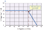
Is this the way the graph is supposed to come? I even tried for lower values of AC magnitude and DC current but still the same kind of plot is occurring. Becoz i thought when we calculate freq response and determine the 3dB the plot is supposed to be something like this right. There is no 0 dB also to start from in my plot.
opamp5.gif... Pls help
 
Last edited:

I was finally able to get the 3dB plot starting from 0. But my only question is i had to set the AC magnitude of one input to 1V and another input to 300nA DC. Its fine i got the plot but my question is the circuit has high linearity error when the input range goes more than -350nA to 350nA. So this is my dynamic range that i determined when i did DC analysis. Though i am able to get the ac response now i have set AC magnitude to 1 A exceeding 350nA range. I don't understand this part at all... Kindly ignore the previous post of mine. The plot occured wrong becoz i missed out a small setting in the ADE. Can anyone pls help me with this doubt. Thank you!!!
 

Hi,

The reason for setting AC magnitude to 1 is to simplify our calculations.. Actually It is called small signal analysis, moreover It is done by normalizing the values.

It doesn't mean you are giving 1A/1V input ... and another thing is AC analysis is done with the given DC common mode range.

So the procedure for doing an AC analysis is set the DC common mode for both inputs. and Give AC input of one input to 1. and run the analysis.

Thanks.
 
The following is the graph is what i obtained.
The green line is mag vs freq and red line is dB20 vs freq
View attachment 123606

Is this the way the graph is supposed to come? I even tried for lower values of AC magnitude and DC current but still the same kind of plot is occurring. Becoz i thought when we calculate freq response and determine the 3dB the plot is supposed to be something like this right. There is no 0 dB also to start from in my plot.
View attachment 123607... Pls help

gain_vs_frequency.jpg The upper frequency limit is a bit more than 7MHz.
 

Status
Not open for further replies.

Part and Inventory Search

Welcome to EDABoard.com

Sponsor

Back
Top