Continue to Site

Welcome to EDAboard.com

Welcome to our site! EDAboard.com is an international Electronics Discussion Forum focused on EDA software, circuits, schematics, books, theory, papers, asic, pld, 8051, DSP, Network, RF, Analog Design, PCB, Service Manuals... and a whole lot more! To participate you need to register. Registration is free. Click here to register now.

32 bit PIC maximum IO changing speed

Status
Not open for further replies.

strahd_von_zarovich

Advanced Member level 4
Full Member level 1
Joined
Sep 25, 2015
Messages
119
Helped
1
Reputation
2
Reaction score
3
Trophy points
1,298
Activity points
2,475
Hi , i want to know how fast i can change my output pin's state. It's system clock is 80MHz and peripheral clock is 10 MHz .
 

As fast as the instructions to change the pin can execute.

The pins can be set, reset ortoggled with a single instruction but if you want to do it continuously you have to take into account the time for the action to repeat. Depending on the language you use that can be as little as two instructions: BTG followed by a jump back to it.

Brian.
 

Thanks for the reply , with the code below i can see max 312kHz , with peripheral clock 10 Mhz how can it be so low ? :-|

Code:
#include <plib.h>


#define SYSCLOCK                            ( 80000000UL )          
#define PERCLOCK                            ( 10000000UL )          
#define	cntMsDelay	1

#pragma config FNOSC = PRIPLL
#pragma config POSCMOD = EC
#pragma config FPLLIDIV = DIV_2
#pragma config FPLLMUL = MUL_20
#pragma config FPLLODIV = DIV_1
#pragma config FPBDIV = DIV_8

#pragma config FWDTEN = OFF
#pragma config CP = OFF
#pragma config BWP = OFF
#pragma config PWP = OFF

void DelayInit()	
{
	unsigned int tcfg;

	/* Configure Timer 1. This sets it up to count a 10Mhz with a period of 0xFFFF
	*/
	tcfg = T1_ON|T1_IDLE_CON|T1_SOURCE_INT|T1_PS_1_1|T1_GATE_OFF|T1_SYNC_EXT_OFF;
	OpenTimer1(tcfg,0xFFFF);   //FFFF

}

void DelayMs(int cms)
{
	int		ims;

	for (ims=0; ims<cms; ims++) {
		WriteTimer1(0);
		while (ReadTimer1() < cntMsDelay);
	}

}

int main()
{
    DelayInit();
    
    PORTSetPinsDigitalOut (IOPORT_B, BIT_10|BIT_11| BIT_12|BIT_13);
    PORTClearBits(IOPORT_B, BIT_10|BIT_11| BIT_12|BIT_13);
    
    while(1){
    
        PORTWrite(IOPORT_B, BIT_10);
        PORTClearBits(IOPORT_B, BIT_10);
    }
    return 0;
}
 

Look at it this way:
Code:
PORTWrite(IOPORT_B, BIT_10);
is a function call, it saves the return address and possibly other variables to the stack, copies the value of IOPORT_B and BIT_10 to the stack, then calls the function which retrieves the values and executes the instructions to write to the port, it then retrieves the return address and takes the return value (which you safely ignore) and passes it to the program.
Code:
PORTClearBits(IOPORT_B, BIT_10);
is also a function call, it does exactly the same process but executes instructions to clear the bits instead.

Then you loop back to the 'While()' instruction and check the value in the brackets before jumping back to the write instruction again. In other words, the processor may be running fast but you are executing a lot more instructions than you think and each of them takes time to execute.

I'm not sure which compiler you are using so I can't give exact syntax but try inserting assembler instruction 'BTG IOPORT_B,10' instead of the two lines in the while(1) loop and see what happens.

Brian.
 
Hi , i want to know how fast i can change my output pin's state. It's system clock is 80MHz and peripheral clock is 10 MHz .

Possibly 5MHz toggle speed with Assembly Code.

Code:
#pragma config POSCMOD = EC

Are you using external clock ?
 
Last edited:
The loop takes actually 30 instruction cycles, corresponding to 0.375 µs at 80 MHz clock according to MPLAB SIM and stopwatch, C32 compiled without any optimizations. But without prefetch and caching enabled, executing the code from flash can take much longer.

Try with these settings:
Code:
// enable cacheability for KSEG0
CheKseg0CacheOn();
// configure the cache for prefetch and 2 wait-state operation */
mCheConfigure(CHE_CONF_WS2 | CHE_CONF_PF_C);
 

Yes , i know other processes are executed but i didn't really think that it would effect that much. I am using MplabX with XC32 compiler , Port functions are from ports.h library which is inside plib.h.

'BTG IOPORT_B,10' is like a toggle function i think . I used PORTToggleBits function but it is slower than sum of write and clear functions . I think i must use low level functions or direct commands.

- - - Updated - - -

- - - Updated - - -

Possibly 5MHz toggle speed with Assembly Code.

Code:
#pragma config POSCMOD = EC

Are you using external clock ?

Yes i am using MX4 ck demo board which has 8 MHz oscillator on it.
 

@strahd_von_zarovich

Instead of using function load data directly to the LAT register for better speed.

Note: Don't expect 50% duty cycle due to loop instruction delays (Increase number of LATB assignment statements for better result)

Something like this

Code:
 while(1)
        {

            LATB = 0xFFFFFFFF;
            LATB = 0x00000000;
...
.
....
.
.
.
..

            LATB = 0xFFFFFFFF;
            LATB = 0x00000000;
        }


For a 117KHz clock I got arounmd 23.5KHz something acceptable.
Clock 473Khz -> toggle speed 95KHz.

ie., toggle freq = sys_clock/4.9

or sys_clock/2.45 toggles. Impressive right ? (Up to 30MHz only, due to flash speed limitation. enable cache for better results)
 
Last edited:
PIC32 has dedicated CLR, SET and INV registers associated with each port register, e.g. LATB, so that setting or resetting port bits can be performed in a single instruction.

Enabling prefetch and caching is necessary nevertheless.
 
Hi and thank you for your replies. Using LATB i can see 2 MHz , but what i need to do is bitbanging at speed of at least 1 MHz which looks look like nearly impossible. Because i need to use other functions like delay(first Data then clock ....) . Is there a way to do this, my delay functions run to slowly.

Code:
#define	cntMsDelay	1

void DelayInit()	
{
	unsigned int tcfg;

	/* Configure Timer 1. This sets it up to count a 10Mhz with a period of 0xFFFF
	*/
	tcfg = T1_ON|T1_IDLE_CON|T1_SOURCE_INT|T1_PS_1_1|T1_GATE_OFF|T1_SYNC_EXT_OFF;
	OpenTimer1(tcfg,0xFFFF);   //FFFF

}

void DelayMs(int cms)
{
	int		ims;

	for (ims=0; ims<cms; ims++) {
		WriteTimer1(0);
		while (ReadTimer1() < cntMsDelay);
	}

}
 

It's difficult to decide if your intended application is feasible without knowing all details. But there's room for optimization in many regards, e.g. using the core timer for delays, not writing the timer.

PIC32/MIPS is a complex device, it takes more than a few days to understand how to utilize it. By the way, did you check the prefetch/cache point?

I must load data to the PLL IC's shift register. I ll send data informations to the PIC using UART then it changes PLL's registers repeatedly according to the data information . I don't really know what does prefetch/cache point mean. I'll look that .
 

Can't you use hardware SPI instead of bit-banging to send the data?

My suggestion was to try the settings in post #6. If they have any effect you are probably motivated to read about prefetch and caching.
 
Hi and thank you for your replies. Using LATB i can see 2 MHz , but what i need to do is bitbanging at speed of at least 1 MHz which looks look like nearly impossible. Because i need to use other functions like delay(first Data then clock ....) . Is there a way to do this, my delay functions run to slowly.

Code:
#define	cntMsDelay	1

void DelayInit()	
{
	unsigned int tcfg;

	/* Configure Timer 1. This sets it up to count a 10Mhz with a period of 0xFFFF
	*/
	tcfg = T1_ON|T1_IDLE_CON|T1_SOURCE_INT|T1_PS_1_1|T1_GATE_OFF|T1_SYNC_EXT_OFF;
	OpenTimer1(tcfg,0xFFFF);   //FFFF

}

void DelayMs(int cms)
{
	int		ims;

	for (ims=0; ims<cms; ims++) {
		WriteTimer1(0);
		while (ReadTimer1() < cntMsDelay);
	}

}

Either use core timer or use some Nop(); delays.
 

Can't you use hardware SPI instead of bit-banging to send the data?

My suggestion was to try the settings in post #6. If they have any effect you are probably motivated to read about prefetch and caching.
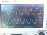
8-O , after changing settings according to yours now i can see 4 MHz . But signal is little weird , what is the reason of capacitive effect ? And why some of the peaks look like 2 quantities?

Where can i find the documents about prefetch and caching , are they in 32MX data sheet ? I can use SPI , but isnt it a protocol , can i use it for loading data to shift register ?
IMG_4414.JPG
 

Waveform looks like large capacitive load or inappropriate probes. Pulse widths are apparently slightly varying, can have many reasons. Normal operation with software based timing.

See PIC reference manual, section 4 prefetch, also MIPS Cache Configuration Application Note and MIPS32® M4K™ Processor Core Software User’s Manual.

SPI is primarly a synchronous serial interface, clock + rx/tx data. Can be used for various applications.
 
I can use SPI , but isnt it a protocol , can i use it for loading data to shift register ?
The way SPI works is to take the value you place into the buffer which is then used as a shift-register and clocked out, one bit at a time (normally MSB first). The 'other' device' uses the clock pulses to know when to read the signal from the first device which it loads into a shift register. AS both devices do the same thing (i.e. they send and receive a bit on each clock pulse), SPI is typically seen as an 'exchange' process.
Depending on what the 'shift register' is that you are referring to (looking back through this thread, I cannot see any reference to a device other than an MPU) you might be able to use the SPI signals directly from the SPI master with some hardware device.
Susan
 
Status
Not open for further replies.

Similar threads

Part and Inventory Search

Welcome to EDABoard.com

Sponsor

Back
Top