Continue to Site

Welcome to EDAboard.com

Welcome to our site! EDAboard.com is an international Electronics Discussion Forum focused on EDA software, circuits, schematics, books, theory, papers, asic, pld, 8051, DSP, Network, RF, Analog Design, PCB, Service Manuals... and a whole lot more! To participate you need to register. Registration is free. Click here to register now.

[PIC] Xbee with SoftUart on PIC18F452

Status
Not open for further replies.

adwnis123

Full Member level 4
Full Member level 4
Joined
Jun 19, 2014
Messages
214
Helped
0
Reputation
0
Reaction score
1
Trophy points
18
Activity points
1,737
Hello, I have the below connection:

A PIC is connected to a Xbee through UART. And my Laptop is connected to another Xbee.

When I use Hardware UART on the PIC (16 MHz,38400bps), the messages are sent correctly to the Laptop.

However, when I use use Software UART on the PIC (16 MHz,38400bps), the messages are NOT sent correctly, I get strange characters.

I use the PIC18F452.

What is wrong?
 

Typically Soft UARTs support significantly lower baud rates in comparison to hardware UARTs.

A baud rate of 38,400 is considerably higher than most Soft UARTs are able to support reliably on a device like the PIC18F452.

Try reconfiguring the serial link on both sides, PC, microcontroller and associated XBees with a baud rate of 9600 or 4800, I suspect the issues you describe maybe resolved.

Why not use the hardware UART module on the PIC18F452? Is it currently being used for another task? If so, you maybe able to utilize an analog multiplexer to switch the connection from XBee to the other device on a periodic and scheduled basis.

There are also, external UART devices available which typically are interfaced and controlled via SPI, however cost benefit analysis typically indicates the choice to employ another model of microcontroller which provides more UARTs is a more prudent decision.


BigDog
 
hello,

With Hardware UART , you have an internal buffer of 1 car...
with sof tuart you don't have...

are you using interrupt on otherfunction (like Timer )?
soft uart need 100% of CPU.
 
By "1 car" you mean I have a lot of space?

So, If I need the HardwareUART to work on 38400bps and the Software on 4800 bps with 16 MHz is it achievable??

- - - Updated - - -

hello,

With Hardware UART , you have an internal buffer of 1 car...
with sof tuart you don't have...

are you using interrupt on otherfunction (like Timer )?
soft uart need 100% of CPU.

I use the hardware UART in parallel with the software UART.
 

"1 car" you mean I have a lot of space?

I believe paulfjujo is indicating the hardware UART has a single character buffer, where as the soft UART has no buffer of any size.

As paulfjujo indicated, soft UARTs require the processor to continuously execute the code implementing the soft UART versus a hardware UART module which has it's own logic to perform many of the required tasks during transmission and reception of data.

Soft UART must generate overclocking to implement the UART task, the frequency of this overclocking is several multiples of the actual baud rate, in a hardware implementation asynchronous serial communications typically utilize an overclocking of 16x or 64x, many soft UARTs overclock at 4x or higher. Therefore, the required processor taskload is significantly greater than simply moving data at the prescribed baud rate.


BigDog
 
If so, you maybe able to utilize an analog multiplexer to switch the connection from XBee to the other device on a periodic and scheduled basis.

Have you worked with any reliable multiplexer you can suggest me ?
 

Have you worked with any reliable multiplexer you can suggest me ?

Most semiconductor manufacturers offer several versions of analog multiplexer devices suitable for UART multiplexing, TI CD405x series and MAXIM MAX399 often come to mind.


CMOS Triple 2-Channel Analog Multiplexer/Demultiplexer with Logic-Level Conversion

You should be able to find examples of the TI CD4053B used as a UART multiplexor with a Google search.


Although, I typically avoid the use of multiplexors for switching UART lines and opt instead for a microcontroller with more UARTs.


BigDog

Because I am confused of how are written here in microchip's datasheet, does this
https://www.microchip.com/wwwproducts/Devices.aspx?product=PIC18F4455

has 2 UARTS? It says 1-A/E/USART.
 
Last edited:

Because I am confused of how are written here in microchip's datasheet, does this

https://www.microchip.com/wwwproducts/Devices.aspx?product=PIC18F4455

has 2 UARTS? It says 1-A/E/USART.

No, the nomenclature, 1-A/E/USART, indicates a single peripheral module which has Advanced Enhanced Synchronous capabilities, which microchip refers to as EUSART, in other words it supports synchronous protocols, as well as, asynchronous protocols.

Reference: PIC18F2X1X/4X1X Datasheet, Section: 17.0 ENHANCED UNIVERSAL SYNCHRONOUS RECEIVER TRANSMITTER (EUSART), Page: 193
The Enhanced Universal Synchronous Asynchronous
Receiver Transmitter (EUSART)
module is one of the
two serial I/O modules. (Generically, the USART is also
known as a Serial Communications Interface or SCI.)

The EUSART can be configured as a full-duplex
asynchronous system that can communicate with
peripheral devices, such as CRT terminals and
personal computers. It can also be configured as a half-
duplex synchronous system that can communicate
with peripheral devices, such as A/D or D/A integrated
circuits, serial EEPROMs, etc.

The Enhanced USART module implements additional
features, including automatic baud rate detection and
calibration, automatic wake-up on Sync Break recep-
tion and 12-bit Break character transmit. These make it
ideally suited for use in Local Interconnect Network bus
(LIN bus) systems.

The EUSART can be configured in the following
modes:

• Asynchronous (full duplex) with:
- Auto-wake-up on character reception
- Auto-baud calibration
- 12-bit Break character transmission

• Synchronous – Master (half duplex) with
selectable clock polarity

• Synchronous – Slave (half duplex) with selectable
clock polarity

By the way, TI offers numerous multiplexor switching devices, the CD405x series is an old standby, there are several other devices which they offer that could suffice in switching UART lines.


BigDog
 
No, the nomenclature, 1-A/E/USART, indicates a single peripheral module which has Advanced Enhanced Synchronous capabilities, which microchip refers to as EUSART, in other words it supports synchronous protocols, as well as, asynchronous protocols.

Reference: PIC18F2X1X/4X1X Datasheet, Section: 17.0 ENHANCED UNIVERSAL SYNCHRONOUS RECEIVER TRANSMITTER (EUSART), Page: 193


By the way, TI offers numerous multiplexor switching devices, the CD405x series is an old standby, there are several other devices which they offer that could suffice in switching UART lines.


BigDog

So I can use A/E/USART as UART. And the 1 UART the PIC has. So I finally have 2 hardware UARTs, right?
 

No, these devices have only one EUSART, there is only one module which can either be configured as 1-UART, or a 1-A/E/USART.

1-UART, 1-A/E/USART,

Notice only one description has an S

If you examine FIGURE 1-2: PIC18F4410/4415/4510/4515/4610 (40/44-PIN) BLOCK DIAGRAM on page 14, you notice there is only one EUSART pictured on the block diagram.


Although, I agree the device page is misleading.

Use the MAPS feature to select devices with specific features:

Microchip Advanced Part Selector

It lists all available features for a specific device more clearly on the right side of the page. You can also specify the minimum number of a specific feature/peripheral module on the left and selector will automatically remove any devices from the list which do not meet your criteria.


BigDog
 

Most semiconductor manufacturers offer several versions of analog multiplexer devices suitable for UART multiplexing, TI CD405x series and MAXIM MAX399 often come to mind.


CMOS Triple 2-Channel Analog Multiplexer/Demultiplexer with Logic-Level Conversion

You should be able to find examples of the TI CD4053B used as a UART multiplexor with a Google search.


Although, I typically avoid the use of multiplexors for switching UART lines and opt instead for a microcontroller with more UARTs.


BigDog

Finally I chose MAX399, but in the datasheet
https://datasheets.maximintegrated.com/en/ds/MAX398-MAX399.pdf

it says
V+ = 5 Volt,
V- = -5 Volt.

The problem is I use 0-5 Volt Supply voltage. How will I take the -5 Volt?

Thank you!
 

hello,

So, If I need the HardwareUART to work on 38400bps and the Software on 4800 bps with 16 MHz is it achievable??

Maybe it is possible ;if your flow of data is not contineous ( some gap of time beween stream)

is your RB0 pin available ?
in this case you can use RB0as RX pin ; and RB0 interrupt to detect incoming of data and treat the data on the way (bit bang UART)
and your main program is not allways busy for that..
4800 bauds -> 480 car /sec .. interrupt every 2mS

How many car /sec do you need .. gives the remaining time for oiher task ...
 

hello,


Maybe it is possible ;if your flow of data is not contineous ( some gap of time beween stream)

is your RB0 pin available ?
in this case you can use RB0as RX pin ; and RB0 interrupt to detect incoming of data and treat the data on the way (bit bang UART)
and your main program is not allways busy for that..
4800 bauds -> 480 car /sec .. interrupt every 2mS

How many car /sec do you need .. gives the remaining time for oiher task ...


Yes, the RB0 is availiable. I thought it. I am going to use uart expansion circuit with MAX399. Because software UART does not work. Do you know any cheap circuit to get -5 Volt supply for MAX399?
 

Did you consider a newer PIC18 with two UARTs like 18F45K22?

Hello, my programmer does not support it, that's why I followed the other solution.
 

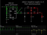
The problem is I use 0-5 Volt Supply voltage. How will I take the -5 Volt?

Thank you!

Start with a positive DC pulse generator. Feed it to a voltage doubler whose diodes are oriented to produce a negative supply.

 
Hello, I have the below connection:

A PIC is connected to a Xbee through UART. And my Laptop is connected to another Xbee.

When I use Hardware UART on the PIC (16 MHz,38400bps), the messages are sent correctly to the Laptop.

However, when I use use Software UART on the PIC (16 MHz,38400bps), the messages are NOT sent correctly, I get strange characters.

I use the PIC18F452.

What is wrong?

Code:
void sendbyte(byte dat)
{
int i;
 
   output_low(pin_d0);   
     delay_us(18);  
   
   for(i=0;i<8;i++)
   {
     if(bit_test(dat,i))
       output_high(pin_d0);
     else
      output_low(pin_d0);     
     delay_us(18);  
   }    
   
   output_high(pin_d0);
}

This piece of code works fine on PIC16F877A (@16Mhz). Actual bit width is 26us for 38400 baud. Considering instruction execution time delay should be less than 26us.

1. Adjust delay values (trial and error) or use assembly for high precision values.
2. It is not a ready to use code/function, you have to adjust delay to get acceptable result. Delay value may vary with compilers and compiler optimization levels.
3. Same logic can be implemented for RX function (int0 + function)
4. Use PLL and operate pic at high freq for better results.
uart.png
Proteus simulation result

Code:
      delay_ms(100);     
      sendbyte(0Xaa);
      delay_ms(100); 
      sendbyte(0X55);
 
How about using a SPI UART like the MAX3107? You have a SPI controller available on the chip.

A soft uart of higher speed will use a lot of the available capacity of your micro. Using an interrupt driven soft uart may cause glitches in both the data stream of both the UARTs. A bit banging solution with delays is worse, since you need to turn off interrupt to get the correct timing.
 
Status
Not open for further replies.

Similar threads

Part and Inventory Search

Welcome to EDABoard.com

Sponsor

Back
Top