Continue to Site

Welcome to EDAboard.com

Welcome to our site! EDAboard.com is an international Electronics Discussion Forum focused on EDA software, circuits, schematics, books, theory, papers, asic, pld, 8051, DSP, Network, RF, Analog Design, PCB, Service Manuals... and a whole lot more! To participate you need to register. Registration is free. Click here to register now.

[SOLVED] 4N25 model in LTSpice, CTR too high?

Status
Not open for further replies.

DanyR

Member level 3
Member level 3
Joined
Aug 23, 2015
Messages
67
Helped
6
Reputation
12
Reaction score
6
Trophy points
8
Location
Nieuwpoort, Belgium
Activity points
677
I discovered that the 4N25 model delivered with LTSpice IV (v4.23g) gives a CTR of 74% (measured in a LTSpice simulation), while the typical CTR (acc the datasheet) is 50%, and the minimum CTR is 20%.

So, why did they choose such a high value in the model?

Reference project: https://www.edaboard.com/threads/345069/#post1473941
 

Hi,

there are several manufacturers for the 4N25.

Some just specify a minimum CTR. So 74 is within spec.

Toshiba datasheet says ctr= 100typical.

***
Maybe this is thae cause for the confusion.

Anyway, it is a optocoupler for digital informations. Here you typically use a lot of overdrive causing saturation and don´t go to the ctr limit.

There are special analog (linear) optocouplers where you operate it in the linear region. Non saturating. Here the CTR is more detailed specified.

Klaus
 
  • Like
Reactions: DanyR

    DanyR

    Points: 2
    Helpful Answer Positive Rating
The minimum CTR is the only parameter which we should consider for use in applications working saturated. Considering that manufacturers specify CTR within a wide range, a simulation would not give a reliable result for a linear region.
 
  • Like
Reactions: DanyR

    DanyR

    Points: 2
    Helpful Answer Positive Rating
Somebody had to pick a value, and they did. Might have
come from the mfr's SPICE modeling folks or been a WAG.
In any case, margining / worst casing is on you.
 
  • Like
Reactions: DanyR

    DanyR

    Points: 2
    Helpful Answer Positive Rating
Somebody had to pick a value, and they did. Might have
come from the mfr's SPICE modeling folks or been a WAG.
Thanks.

In any case, margining / worst casing is on you.
Yes, indeed.
To be able to do my tests I had to make a model of a (very) generic (very rudimentary) optocoupler with transistor output and settable CTR. Perhaps it can be usefull for other users.

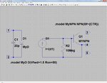
This is the circuit diagram of OptoC:
OptoC.jpg

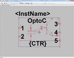
This is the symbol of OptoC:
OptoC_Symbol.jpg

The files of the OptoC symbol:
View attachment OptoC.zip

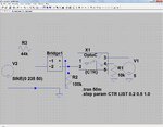
An example of its usage (zero crossing detector here):
ZeroCrossingExample.jpg
View attachment Draft5.zip

As you can see you can set the CTR value (1 means 100%) in the diagram that uses OptoC. In the example the CTR is set to 3 different values: 20%, 50% and 100%.
 
Good job. Consider submitting it to the Yahoo! LTSpice
user group for their contrib models archive.
 

Status
Not open for further replies.

Similar threads

Part and Inventory Search

Welcome to EDABoard.com

Sponsor

Back
Top