fahad.joharji
Newbie level 3
Hi everyone
I have an issue with my PIC16F1509 MUC and 16x2 LCD,when i input the program from MikroC software to my PIC16F1509 the display was like blocks (like the code does not work). However, when I try the same LCD and same code (different pins number ) with PIC16F877A MUC it was work correctly. I am used external oscillator when I use PIC16F877A.
I am using the internal oscillator in PIC16F1509 and I changed the frequency to 8MHz (the default was 500KHz regarding the datasheet) by using this code:
OSCCON=0b01110000;
I am actually tried to make simple LED blinking program on PIC16F1509, and it was work correctly.
Here my code for PIC16F1509 (doesn't work):
Here my code for PIC16F877A (worked):
I have already checked all the connections several times and it didn't work:-?:-x
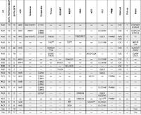
Here image for the PIC16F1509 pin out (May help)
Hope someone will help me to solve this
THANKS
- - - Updated - - -
Also can I used ADC pins...... I don't know how to change the pin to general purpose:|
I have an issue with my PIC16F1509 MUC and 16x2 LCD,when i input the program from MikroC software to my PIC16F1509 the display was like blocks (like the code does not work). However, when I try the same LCD and same code (different pins number ) with PIC16F877A MUC it was work correctly. I am used external oscillator when I use PIC16F877A.
I am using the internal oscillator in PIC16F1509 and I changed the frequency to 8MHz (the default was 500KHz regarding the datasheet) by using this code:
OSCCON=0b01110000;
I am actually tried to make simple LED blinking program on PIC16F1509, and it was work correctly.
Here my code for PIC16F1509 (doesn't work):
Code C - [expand] 1 2 3 4 5 6 7 8 9 10 11 12 13 14 15 16 17 18 19 20 21 22 23 24 25 26 27 28 29 30 31 32 33 34 35 36 37 38 39 40 41 42 43 44 45 46 47 48 49 50 51 52 53 54 55 56 57 58 59 60 61 62 63 64 65 // LCD module connections sbit LCD_RS at RC1_bit; sbit LCD_EN at RC2_bit; sbit LCD_D4 at RC4_bit; sbit LCD_D5 at RC5_bit; sbit LCD_D6 at RB6_bit; sbit LCD_D7 at RB7_bit; sbit LCD_RS_Direction at TRISC1_bit; sbit LCD_EN_Direction at TRISC2_bit; sbit LCD_D4_Direction at TRISC4_bit; sbit LCD_D5_Direction at TRISC5_bit; sbit LCD_D6_Direction at TRISB6_bit; sbit LCD_D7_Direction at TRISB7_bit; // End LCD module connections char txt1[] = "mikroElektronika"; char txt2[] = "EasyPIC6"; char txt3[] = "Lcd4bit"; char txt4[] = "example"; char i; // Loop variable void Move_Delay() { // Function used for text moving Delay_ms(500); // You can change the moving speed here } void main(){ C1ON_bit = 0; // Disable comparators C2ON_bit = 0; OSCCON=0b01110000; // To change the internal frequency to 8 MHz Lcd_Init(); // Initialize LCD Lcd_Cmd(_LCD_CLEAR); // Clear display Lcd_Cmd(_LCD_CURSOR_OFF); // Cursor off Lcd_Out(1,6,txt3); // Write text in first row Lcd_Out(2,6,txt4); // Write text in second row Delay_ms(2000); Lcd_Cmd(_LCD_CLEAR); // Clear display Lcd_Out(1,1,txt1); // Write text in first row Lcd_Out(2,5,txt2); // Write text in second row Delay_ms(2000); // Moving text for(i=0; i<4; i++) { // Move text to the right 4 times Lcd_Cmd(_LCD_SHIFT_RIGHT); Move_Delay(); } while(1) { // Endless loop for(i=0; i<8; i++) { // Move text to the left 7 times Lcd_Cmd(_LCD_SHIFT_LEFT); Move_Delay(); } for(i=0; i<8; i++) { // Move text to the right 7 times Lcd_Cmd(_LCD_SHIFT_RIGHT); Move_Delay(); } } }
Here my code for PIC16F877A (worked):
Code C - [expand] 1 2 3 4 5 6 7 8 9 10 11 12 13 14 15 16 17 18 19 20 21 22 23 24 25 26 27 28 29 30 31 32 33 34 35 36 37 38 39 40 41 42 43 44 45 46 47 48 49 50 51 52 53 54 55 56 57 58 59 60 61 62 // LCD module connections sbit LCD_RS at RB4_bit; sbit LCD_EN at RB5_bit; sbit LCD_D4 at RB0_bit; sbit LCD_D5 at RB1_bit; sbit LCD_D6 at RB2_bit; sbit LCD_D7 at RB3_bit; sbit LCD_RS_Direction at TRISB4_bit; sbit LCD_EN_Direction at TRISB5_bit; sbit LCD_D4_Direction at TRISB0_bit; sbit LCD_D5_Direction at TRISB1_bit; sbit LCD_D6_Direction at TRISB2_bit; sbit LCD_D7_Direction at TRISB3_bit; // End LCD module connections char txt1[] = "mikroElektronika"; char txt2[] = "EasyPIC6"; char txt3[] = "Lcd4bit"; char txt4[] = "example"; char i; // Loop variable void Move_Delay() { // Function used for text moving Delay_ms(500); // You can change the moving speed here } void main(){ Lcd_Init(); // Initialize LCD Lcd_Cmd(_LCD_CLEAR); // Clear display Lcd_Cmd(_LCD_CURSOR_OFF); // Cursor off Lcd_Out(1,6,txt3); // Write text in first row Lcd_Out(2,6,txt4); // Write text in second row Delay_ms(2000); Lcd_Cmd(_LCD_CLEAR); // Clear display Lcd_Out(1,1,txt1); // Write text in first row Lcd_Out(2,5,txt2); // Write text in second row Delay_ms(2000); // Moving text for(i=0; i<4; i++) { // Move text to the right 4 times Lcd_Cmd(_LCD_SHIFT_RIGHT); Move_Delay(); } while(1) { // Endless loop for(i=0; i<8; i++) { // Move text to the left 7 times Lcd_Cmd(_LCD_SHIFT_LEFT); Move_Delay(); } for(i=0; i<8; i++) { // Move text to the right 7 times Lcd_Cmd(_LCD_SHIFT_RIGHT); Move_Delay(); } } }
I have already checked all the connections several times and it didn't work:-?:-x
Here image for the PIC16F1509 pin out (May help)
Hope someone will help me to solve this
THANKS
- - - Updated - - -
Also can I used ADC pins...... I don't know how to change the pin to general purpose:|
Last edited by a moderator: