Continue to Site

Welcome to EDAboard.com

Welcome to our site! EDAboard.com is an international Electronics Discussion Forum focused on EDA software, circuits, schematics, books, theory, papers, asic, pld, 8051, DSP, Network, RF, Analog Design, PCB, Service Manuals... and a whole lot more! To participate you need to register. Registration is free. Click here to register now.

25MHz LPF help with design

Status
Not open for further replies.

neazoi

Advanced Member level 6
Joined
Jan 5, 2008
Messages
4,155
Helped
13
Reputation
26
Reaction score
15
Trophy points
1,318
Location
Greece
Activity points
37,164
Hello, can you please help me design a LPF for 25MHz (50R)
I need it to be quite sharp, in the sense that I need to attenuate the >= 28MHz quite a lot.
Thanks
 

You know that a passband ripple and stopband attenuation specification is necessary to finish the design.
 
  • Like
Reactions: neazoi

    neazoi

    Points: 2
    Helpful Answer Positive Rating
Hello, can you please help me design a LPF for 25MHz (50R)
I need it to be quite sharp, in the sense that I need to attenuate the >= 28MHz quite a lot.
Thanks

FILTER.JPG

you can try this toplogy first.

Because 25 MHz is too close to 28 MHz,

It is difficult to achieve low insertion loss for 25 MHz and high attenuation for 28 MHz simultaneously.

Thus, maybe you should use BPF rather than LPF.
 
Last edited:
  • Like
Reactions: neazoi

    neazoi

    Points: 2
    Helpful Answer Positive Rating
View attachment 122035

you can try this toplogy first.

Because 25 MHz is too close to 28 MHz,

It is difficult to achieve low insertion loss for 25 MHz and high attenuation for 28 MHz simultaneously.

Thus, maybe you should use BPF rather than LPF.

No, not a bandpass filter. It has to cut-out all frequencies above 25MHz not below. It will be used as a filter in a 14MHz-25MHz 1W transmitter, so the second harmonic of 14MHz which is 28MHz (and frequencies above that of course), has to be cut quite well.
I think I have space onto the PCB for 2-3 T50-2 cores.

- - - Updated - - -

You know that a passband ripple and stopband attenuation specification is necessary to finish the design.

See the post above, I do not have specific requirements, as long as the passband ripple is kept low (<0.5db or less?) and the stopband attenuation as high as possible. I consider the 28MHz first for the reasons explained above and because it is the first HAM band (harmonic of 14MHz) that needs to be cut first. The higher harmonics should be easier attenuated anyway because they are more within the filter's cut.
 

No, not a bandpass filter. It has to cut-out all frequencies above 25MHz not below. It will be used as a filter in a 14MHz-25MHz 1W transmitter, so the second harmonic of 14MHz which is 28MHz (and frequencies above that of course), has to be cut quite well.
I think I have space onto the PCB for 2-3 T50-2 cores.

- - - Updated - - -


See the post above, I do not have specific requirements, as long as the passband ripple is kept low (<0.5db or less?) and the stopband attenuation as high as possible. I consider the 28MHz first for the reasons explained above and because it is the first HAM band (harmonic of 14MHz) that needs to be cut first. The higher harmonics should be easier attenuated anyway because they are more within the filter's cut.


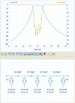
I misunderstood that your center frequency is only 25 MHz.

If so, you can try this BPF firstly.

BPF.JPG

Insertion loss of 14 MHz : 0.237 dB
Insertion loss of 25 MHz : 0.475 dB
Insertion loss of 28 MHz : 24.4 dB


Thus, this topology makes you posses acceptable insertion loss for passband and acceptable rejection for 28 MHz.

As mentioned above, 25 MHz is too close to 28 MHz.

Compared to BPF, it’s difficult for LPF to achieve low insertion loss @ 25 MHz and high rejection @ 28 MHz simultaneously.
 
  • Like
Reactions: neazoi

    neazoi

    Points: 2
    Helpful Answer Positive Rating
I misunderstood that your center frequency is only 25 MHz.

If so, you can try this BPF firstly.

View attachment 122038

Insertion loss of 14 MHz : 0.237 dB
Insertion loss of 25 MHz : 0.475 dB
Insertion loss of 28 MHz : 24.4 dB


Thus, this topology makes you posses acceptable insertion loss for passband and acceptable rejection for 28 MHz.

As mentioned above, 25 MHz is too close to 28 MHz.

Compared to BPF, it’s difficult for LPF to achieve low insertion loss @ 25 MHz and high rejection @ 28 MHz simultaneously.

Thank you very very much for your reply!
Maybe I was not very clear in my description, the filter has to have a passband from 1-25MHz, whereas the one you have shown starts from 14MHz.
I apologize it was my mistake.
I thought in terms of harmonics not in terms of passband.
Can you alter this design for me so I can try it?

If it helps you, even a more relaxed attenuation curve (with less inductors used) would be ok as the transmitter harmonics are not very high anyway.

Thanks a lot!
 

Compared to BPF, it’s difficult for LPF to achieve low insertion loss @ 25 MHz and high rejection @ 28 MHz simultaneously.

Completely wrong. A 9th order low-pass filter (Chebyshev I with 0.5 dB bandpass ripple) has similar stopband attenuation than your suggested bandpass, but uses less components.

Is it that your filter tool doesn't support low-pass filters, or didn't you try?
 

Suggestion for Neazoi: Download from http://www.tonnesoftware.com/elsiedownload.html

The free "student edition" should be fine for what you want. Works on Windows, I haven't tried it on Linux yet.

Brian.

I have RFsim99, which is simple and can be used to design simple LC filters. My lack of knowledge in filter parameters (apart from the basics) is why I need the advice from more experienced people.

Is it ok to rely on the filter response curve at the given I/O impedances?

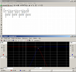
See for example this filter (I have no idea what the blue line is). Eventhough complex, it does not meet the specs as it has too much loss even in the passband.

The previous design suggested was good, but one had to think to put series capacitors in the signal path. I did not know that (or similar "tricks")
 

Attachments

  • Untitled.png
    Untitled.png
    42.8 KB · Views: 137

Thank you very very much for your reply!
Maybe I was not very clear in my description, the filter has to have a passband from 1-25MHz, whereas the one you have shown starts from 14MHz.
I apologize it was my mistake.
I thought in terms of harmonics not in terms of passband.
Can you alter this design for me so I can try it?

If it helps you, even a more relaxed attenuation curve (with less inductors used) would be ok as the transmitter harmonics are not very high anyway.

Thanks a lot!


If your passband is from 1MHz to 25 MHz.

And you hope for less inductors used at the expense of harmonics rejection.

Perhaps you can try the simple 5 order LPF firstly.


LPF.JPG

Insertion loss @ 1MHz : 0.0014 dB
Insertion loss @ 25 MHz : 0.0474 dB
 

If your passband is from 1MHz to 25 MHz.

And you hope for less inductors used at the expense of harmonics rejection.

Perhaps you can try the simple 5 order LPF firstly.


View attachment 122044

Insertion loss @ 1MHz : 0.0014 dB
Insertion loss @ 25 MHz : 0.0474 dB

Oh thanks a lot! that is much better!
 

I have no idea what the blue line is.
Clearly written on the diagram: s11 (reflected signal), see https://en.wikipedia.org/wiki/S_parameters

Eventhough complex, it does not meet the specs as it has too much loss even in the passband.
It's apparently a butterworth filter or similar (no ripple in the passband) with standard cut-off frequency attenuation of 3 dB. Your specification seems to demand a lower cut-off frequency attenuation, if you use a Chebyshev filter prototype, you get cut-off attenuation = ripple maximum by default, e.g. 0.5 dB attenuation for your initial specification. Stopband attenuation does then depend only on the filter order, e.g. about 22.5 dB at 28 MHz for the 9th order filter.

lp.png
 

Clearly written on the diagram: s11 (reflected signal), see https://en.wikipedia.org/wiki/S_parameters


It's apparently a butterworth filter or similar (no ripple in the passband) with standard cut-off frequency attenuation of 3 dB. Your specification seems to demand a lower cut-off frequency attenuation, if you use a Chebyshev filter prototype, you get cut-off attenuation = ripple maximum by default, e.g. 0.5 dB attenuation for your initial specification. Stopband attenuation does then depend only on the filter order, e.g. about 22.5 dB at 28 MHz for the 9th order filter.

View attachment 122049

How about this one?
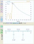
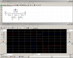
I made some tweaking on the rfsim99. It uses only 3 inductors. The bandpass ripple is 0.26db at worst case. At 24.4MHz it is 0.18db and the attenuation at 28MHz is 10.2db.
Not too bat for such a 3-inductor filter, what do you think?

I do not understand how the blue line should be for a better filter, is it better to be lower or higher in the diagram or it does not matter too much?

- - - Updated - - -


I did some more tweaking attached below (1st picture).
I have also tried varying the input ant output impedances from 20R to 300R. I am pleased to say that the filter response (red line) did not degrade too much. The cut off frequency stayed pretty much the same, only the pass-band ripple varied but this can be compensated in my design (ALC).
If you verify that this filter is ok in general, I will be happy to build it.
 

Attachments

  • Capture.PNG
    Capture.PNG
    49 KB · Views: 156
  • Capture2.PNG
    Capture2.PNG
    48.9 KB · Views: 167
Last edited:

The latest filter is an elliptical (cauer) type which gives higher stopband attenuation by implementing real zeros.

Still not sure what's your actual stopband specification. But apparently you know now how to use the tools to calculate a filter. Very good.
 

The latest filter is an elliptical (cauer) type which gives higher stopband attenuation by implementing real zeros.

Still not sure what's your actual stopband specification. But apparently you know now how to use the tools to calculate a filter. Very good.

That is good news!
I only do not know how this blue line (reflected signal) affects the filter and how it should better be. Should it better be at low values or at high ones? Or it does not matter for the filter response?
This is a more general question about filter design, not dedicated to the specific filter.
 

In a (lossless) LC filter, s11 has a fixed relation to s21, conservation of energy demands s11² + s21² = 1 (reflected + transmitted power = incident power). You'll notice that both lines always intersect at - 3dB. In so far, s11 contains no information that isn't already contained in s21, you can safely ignore the s11 graph.


Status
Not open for further replies.

Similar threads

Part and Inventory Search

Welcome to EDABoard.com

Sponsor

Back
Top