Continue to Site

Welcome to EDAboard.com

Welcome to our site! EDAboard.com is an international Electronics Discussion Forum focused on EDA software, circuits, schematics, books, theory, papers, asic, pld, 8051, DSP, Network, RF, Analog Design, PCB, Service Manuals... and a whole lot more! To participate you need to register. Registration is free. Click here to register now.

Combining two signal using coupler

Status
Not open for further replies.

bejing

Member level 2
Member level 2
Joined
Sep 7, 2015
Messages
42
Helped
0
Reputation
0
Reaction score
0
Trophy points
6
Activity points
330
Hi Everyone.
I have a 4 port quadrature directional coupler. in simple form it has 3dB coupling Coefficient but in general it may have any Arbitrary Coupling Factor, for example 5dB, 10dB, ... .
this coupler has this for terminal: IN, Out1 (0 degree), Out2 (-90 degree), Isolation.
Consider this coupler has Two input at this ports: IN, Iso.
Also consider Out1 and Out2 are output of this network.
I am Applying Two Tones in same Frequency. but the phase and magnitude of these tones are not equal.
what happens in Output Ports?
And can you explain the Math needed to combine these 2 tones?

First I think this simple problem should solved to extend it later for a general form of Arbitrary Variables:
A 3dB Quadrature Coupler, two tones at IN & ISO Ports with these properties:
Tone1: Freq=5GHz, Mag=10dBm, Phase=0 is Applied to Port 1 (IN).
Tone2: Freq=5GHz, Mag=7dBm, Phase=0 is Applied to Port 2 (ISO).

What is The Signal at Port 3 (Out1, 0 degree) and Port 4 (Out2, -90 degree) ??

Thanks For Your Attention,
Bejing.
 

You can't make DC's span from 0 to 5GHz..

Perhaps 0.01G~2GHz not 5 unless very expensive.

Try a mixer

Also 5GHz is not a tone, but it is a signal.
 

You can't make DC's span from 0 to 5GHz..

Perhaps 0.01G~2GHz not 5 unless very expensive.
Thanks for your Help.
I don't get your mean. 5GHz is only an example frequency.
Try a mixer
I don't want to mix these two signals. I only want to add them using a coupler.
Also 5GHz is not a tone, but it is a signal.
isn't 5ghz a frequency tone?
I use it because of ADS uses p_1tone as a power source.

- - - Updated - - -

I think if those two signals were equal and 10dBm & inphase, the output signals also are 10dBm in Amplitude but with 90 degrees phase difference. is it true?

but when two signals at input of these network are inphase but muptiple Amplitudes, I think first I should for example say that sig1 in port1 that passes from main line to the out1 port, has 3dB loss and without any phase change, so it can be 10-3=7dBm and 0 degree.
also sig2 when passes through coupled line to out2 port, experience 3dB loss and -90 degrees back in phase. so it will become 7-3=4dBm and -90 degrees.
then in port 3 or Out1, we have two signals, 7dBm (5mw) and 0 degree.
and 4dBm (2.5mw) and -90 degree.

when combining these two signals that arrive in port3, I can add them in complex format and I can say 5-2.5i. is it true??
 

please help me.
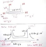
3dBex.jpg
 

can we use a coupler as power combiner?
can we use a coupler as a 4 ports network that get 2 signals as input and reject 2 signals as output?

in an ideal coupler that isolation is extremely, is the Conservation of energy Theorem is valid?
for example if we get a coupler, two signals of 5mw and 10 mw, if we can say the output signals also is 15mw together?
 

I believe, the only open point in your previous post is to calculate the summed output signals.

Some simple vector arithmetic after converting to voltage in cartesian coordinates. Get 8,76 dBm and -35 respectively -54.

I don't exactly understand your latest question. A power combiner would have no reflected power towards the sources. I don't see this property for the discussed hybrid coupler.

Conservation of energy is obviously fulfilled for any passive device with no internal losses.
 
  • Like
Reactions: bejing

    bejing

    Points: 2
    Helpful Answer Positive Rating
I believe, the only open point in your previous post is to calculate the summed output signals.

Some simple vector arithmetic after converting to voltage in cartesian coordinates. Get 8,76 dBm and -35 respectively -54.

I don't exactly understand your latest question. A power combiner would have no reflected power towards the sources. I don't see this property for the discussed hybrid coupler.

Conservation of energy is obviously fulfilled for any passive device with no internal losses.

Your coupler is a directional coupler. It utilizes specific coupling line system that combines input power to outputs over a frequency band PROVIDED all ports are matched. So it is no issue of power conservation- the power is absorbed in a termination while its fraction outputs at another port.
Such couplers are often used in reflectometers as when a termination at output port is not perfect, the reflected power outputs at the secondary port in proportion to the termnation reflection.

Some couplers are designed with 3-dB coupling, so such ones can be used as power dividers (or summing devices if connected backwards).
 
  • Like
Reactions: bejing

    bejing

    Points: 2
    Helpful Answer Positive Rating
Some simple vector arithmetic after converting to voltage in cartesian coordinates. Get 8,76 dBm and -35 respectively -54.
hellow FVM,
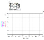
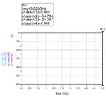
you are great, becuase ADS Also Calculates those Values that you say above, 8.76dBm, -35d, -54d.
but can you explain the details of these simple Math that you get those values? Very Excuseme FVM.
because when i calculate the signal in one of those outputs in picture, i get 2.5-5i and in another output i get 5-2.5i.
that the magnitude and phase of them are: 5.59mw or 7.47dBm and -26d , -63d.

I don't exactly understand your latest question. A power combiner would have no reflected power towards the sources. I don't see this property for the discussed hybrid coupler.
if we have an ideal directional coupler that has no reflected energy and no loss and no power toward isolated port, then s11,s22,s33,s44=better than -30 for example & s13=isolation= better than -30dB. so we can assume when a signal is entering input port, this signal will pass through main and coupled path fairly upon coupled factor and no dissipated energy we have. in this situation, we also can apply a signal to the isolation port simultaneously like port 1. this is my idea for combining issue in a directional coupler.

i will put my ADS project for clarify soon.
thanks very much.
 

can we use a coupler as power combiner?
A power combiner is generally a three port network, while you are discussing a four port coupler. A coupler will indeed combine the power on the P3 and P4 ports, but the output power will be distributed between ports P1 and P2, so it can't really be called a combiner.

If your objective is to combine the power and have it all end up on one output port (so there are only three ports), then the bottom line is that this can only be done efficiently if the amplitude and phase of the inputs meet certain conditions.
 
  • Like
Reactions: bejing

    bejing

    Points: 2
    Helpful Answer Positive Rating
i get 2.5-5i and in another output i get 5-2.5i.
that the magnitude and phase of them are: 5.59mw or 7.47dBm and -26d , -63d.

The fault is to calculate with power quantities. The vectorial summation takes place for voltage quantities. Power is a scalar.
 
  • Like
Reactions: bejing

    bejing

    Points: 2
    Helpful Answer Positive Rating
The fault is to calculate with power quantities. The vectorial summation takes place for voltage quantities. Power is a scalar.
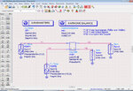
oh thanks, I had a bad mistake. but why ADS has Defined its P_1tone Frequency Source as Power Mag and Power Phase!?

I have Attached the Schematic and Data Display Figures.
1.jpg2.jpg3.jpg4.jpg

- - - Updated - - -

hellow dear mtwieg.
yes combining with a coupler isn't an efficient way. I think this way is most used for have a signal with another signal in different frequency for have a sample of it with the main line signal...
for example for some tests for active devices.
also we may use many couplers in a chained configuration.
 

1. Is the setup wrong?
2. we can calculate voltage (rms) with assumption of 50 ohms system. How to calculate or estimate this combination of signals in a waveguide system that we have not an absolute value for voltage?
Thanks so very much.

I think this application of a coupler or other 4 ports hybrids are an amazing problem!
 

I would primarly ask, what's the setup good for?

I'm confident that ADS can calculate this basic circuit correctly. What should be wrong with it? If at all, there could be unclarities about the coupler specification. In case of doubt, refer to the S matrix.

I don't understand the difference of superimposing signals in a transmission line or waveguide system. Calculations are the same, you don't need to refer to absolute voltage levels, just wave magnitudes and phases.

To mention a practical problem, power combiner operation presumes that both sources are exactly in phase, driven originally by the same generator. Technical applications are parallel operation of power amplifiers or antenna arrays.
 

This setup of coupler that I have mentioned above, can use in a traveling wave tapering. We can make another freedom of degree with using the isolated port of coupler in the game!
 

Status
Not open for further replies.

Part and Inventory Search

Welcome to EDABoard.com

Sponsor

Back
Top