Continue to Site

Welcome to EDAboard.com

Welcome to our site! EDAboard.com is an international Electronics Discussion Forum focused on EDA software, circuits, schematics, books, theory, papers, asic, pld, 8051, DSP, Network, RF, Analog Design, PCB, Service Manuals... and a whole lot more! To participate you need to register. Registration is free. Click here to register now.

What is this circuit?

Status
Not open for further replies.

fredy004

Newbie level 4
Newbie level 4
Joined
Nov 18, 2009
Messages
6
Helped
0
Reputation
0
Reaction score
0
Trophy points
1,281
Activity points
1,321
This circuit is part of altimeter (radar)

I hope someone could help or recognize this circuit.


thanks alot.
 

It is rat race mixer
LO & RF are fed into the ring and the IF comes from the 'cheese' in the centre
 
Thanks alot G4BCH

Its very helpful. Could you refer me to some paper or book on this specific circuit. I don't understand what is radial stub do here.

Thanks again for your help.
 

Google "Rat RAce MIxer" for details. The radial stub is often used in stripline as a RF termination, here at IF (low frequenxy) output.
 
Thanks But I googled it already. Nothing came up usefull. Thanks anyway. Some Referense may help me much more.
 

it is a mixer. It is probably a homodyne radar receiver of some sort. It sends out RF from a transmit antenna. Simultaneously, it sends a copy to one port of this "mixer" called the "local oscillator port". When the return bounces back from the ground, it is received by an antenna and input to the "RF Port" of the mixer. The resultant is a low frequency IF signal that you can use to tell the distance to the ground.

For instance, if you are varying the transmit frequency at a linear ramp rate...by the time the return comes back to the radar, the transmit signal will have moved slightly in frequency. So lets say you transmit at 1.5 GHz, but some time later the return hits and you are now transmitting at 1.5001 GHz. You will end up with a 100 KHz beat note coming out of the IF port of the mixer. The IF port beat note frequency is proportional to round trip distance.
 
Thanks alot biff44

actually I have all image of board but there is many parts.
I upload all images top and bottom of board. I appreciate any help in recognizing each part or block diagram related to this.
here all of board


Thanks alot people
 

it seems to use one antenna. The right side of the microwave circuit is a transmitter, which involves a transistor, and a rather lengthy distributed filter that probably is there to reduce harmonic outputs. the transmit power is sent thru a hybrid coupler (the gold square circuit in the middle). Some of the transmit power leaks to the mixer, and the rest goes out the antenna port. The return power comes back thru that same antenna port, and part of it eventually hits the mixer.
 
Thanks alot biff44

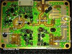
Left of first picture Is this some sort of matching network with short stubs or this is something else.
and Is the 90 hybrid is used for another mixer in this board?
Thanks again for all your help
 

comments.jpg

Left of first picture Is this some sort of matching network with short stubs or this is something else.

All stubs seem to be quarterwave stubs (90 deg). I copied part of radial stub to the right of the image to see relative sizes. Also must keep in mind that radial stubs are shorter than rectangular stubs for same frequency. Quarterwave stubs are shortened to ground using vias, so they act as half-wavelength open stubs (180 deg). At frequency of operation they just work as resonators. It seems that it is second-harmonic oscillator. For example transistor at the bottom right provides 5GHz signal with some 10GHz harmonics. All those stubs will act as 90deg open stubs at 5GHz, so 5GHz would be filtered out.

About your question, i think left part of image is the same as right.
Look at the bottom left - there is transistor for second oscillator. It's output does not go to the antenna, only in rat-race mixer. So chance that unwanted 5GHz will leak outside is small. Right bottom transistor output goes directly to the antenna, so putting more stubs to attenuate 5GHz makes sense.

and Is the 90 hybrid is used for another mixer in this board?
it seems that there is only one mixer here. Rat-race with diode pair.

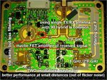
What i cant see is where signal from two oscillators comes to the other side of PCB to be measured. As it is some kind of VCO, there must be some vias here. Maybe top of bottom left transistor, there may be some via. Signal must be provided to PLL before it is filtered, it must be much cheaper.

Also:
comments2.jpg

I imagine it works this way:

Right-bottom oscillator is constant frequency (non-VCO). Of course it's frequency will drift with temperature, but on a short period of time it can be seen as constant-frequency oscillator.

Left-bottom oscillator is VCO (voltage controlled oscillator).

As some portion of first oscillator frequency can leak to mixer, it is possible to measure frequency difference between two oscillators using diode mixer. Some FMCW sensors worked that way, because prescalers was too expensive or unavailable. Or maybe there some PLL chip on the other side of PCB, that somehow connected to left oscillator (i do not see where).
 
Last edited:
Thanks Terminator3

Although simple thanks may be not enough for your big help. Your post is very usefull and I appreciated that. I think I must focus on the other side of the board and hope someone could help with that.

Thanks again for your help.
 

Is there any readable text on IC's used? I see some kind of lacquer everywhere.

From the left to right:
1) some low frequency HC49 quartz oscillator in a shiny package with some IC above it.
It can be some simple microcontroller (like Atmel's attiny ).
Purpose of this microcontroller is usually to send control commands to PLL IC over SPI or I2C.

2) next small chip near bottom left may be LDO regulator or something like this

3) 6 similar size ICs,
two of them with symmetrical short trace on both sides and many caps/resistors - may be an operational amplifiers
Other four: two of them may be PLL chips, and two i can't guess what.

4) small chip with 8 pins near bottom right can be prescaler IC. But it would be strange if good PLL IC is already here (with internal prescaler). Quartz oscillator on the bottom right makes me think that it is another microcontroller like attiny for configuring PLL chips at startup. Then (1) chip would be more like small DSP, but then i would have doubts about available RAM for processing.

5) two big quartz oscillators make me think that there are two separate PLL ICs for each transistor.

6) looking at this board makes you think that there is too many ICs for this task. It gives me an idea that some of this ICs are just a flip-flops, connected in series to form counter. For example upper right part two ICs may be a flip-flops.

If you can read marking on IC's then many things may be cleared out.
 
Status
Not open for further replies.

Part and Inventory Search

Welcome to EDABoard.com

Sponsor

Back
Top