Continue to Site

Welcome to EDAboard.com

Welcome to our site! EDAboard.com is an international Electronics Discussion Forum focused on EDA software, circuits, schematics, books, theory, papers, asic, pld, 8051, DSP, Network, RF, Analog Design, PCB, Service Manuals... and a whole lot more! To participate you need to register. Registration is free. Click here to register now.

162 KHz radio resonnator

Status
Not open for further replies.

Robert_

Newbie level 3
Newbie level 3
Joined
May 1, 2015
Messages
4
Helped
0
Reputation
0
Reaction score
0
Trophy points
1
Activity points
32
Hello,

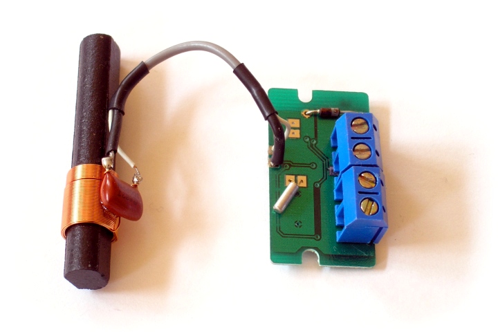
I'd like to make an antenna for the 162 KHz frequency. Do you have some tips to design it ? I have never done that before.
I have a ferrite rod 10mm diameter 100mm long. Is it better to maximise the inductive part or the coupled capacitor ?

Thank you

Bob
 

You can increase signal proportional to
1) wire length of antenna
2) Q of resonator
3) high gain , low noise preamp
4) matched filter to signal bandwidth.

Note in example below, High Q requires low leakage Plastic film Cap. There are also ceramic resonators used with whip antenna
Low_cost_DCF77_receiver.jpg

https://en.wikipedia.org/wiki/Low_frequency#Antennas
https://www.arrl.org/lf-low-frequency
https://en.wikipedia.org/wiki/2200-meter_band#Technical_issues
 
Thank you this picture is exactly what I want to perform.
But there are parameters that I have to choose like length, number of turn and diameter of the copper wire.
After that my idea is to measure my coil with L meter, then choose the appropriate C corresponding for 162 KHz.
Maybe fixed value capacitor + adjustable capacitor in parallel to tune accurately the receiver.
 

The Gain or Q of a parallel tank circuit with high impedance load, R, is as follows;

Q=R√(C/L)

So make L small but long as you can to pickup µV/m signals such as 1m vs 10cm.

But keep L small and use larger C , so that stray capacitance does not detune antenna.

Use Plastic film cap with 100M resistance and front end FET with similar high impedance. Lower Coil impedance will shunt ESD and lighting noise while raising Q.

At resonance antenna impedance=R only but off frequency drops quickly to provide filter gain.

Other methods use impedance gain by series to parallel auto transformer for N factor improvement.

high inductance // tank circuits are used for gain when driven only by current sources or H field coupling, so it depends what on if you are detecting near H fields or far E fields.

for near H fields a large loop is better.
for far E fields a long coil is better.


Open field LF antenna detects E field high is voltage at free space impedance.

Try to choose cap well below 1000 pF for selecting L so that series R of inductor is negligible or high Q inductor ZL/Rs

thats my 2 cents


more..

e.g. 470pF//2.1mH @160kHz =~2.1kOhm so 1MOhm R load might achieve Q=500 if coil Q is higher meaning <2 Ohm Rs.

higher L and smaller C is possible if winding capacitance is lower, but keep in mind antenna is like a transmission impedance transformer between free space and high Z input preamp, so ideal impedance is stepup tuned transformer , otherwise ZL(f)= RMS Z(f) or root of {free space source Z^2 and high R load^2}
 
Thank you ! I will try to do something and share my progress
 

Status
Not open for further replies.

Similar threads

Part and Inventory Search

Welcome to EDABoard.com

Sponsor

Back
Top