Continue to Site

Welcome to EDAboard.com

Welcome to our site! EDAboard.com is an international Electronics Discussion Forum focused on EDA software, circuits, schematics, books, theory, papers, asic, pld, 8051, DSP, Network, RF, Analog Design, PCB, Service Manuals... and a whole lot more! To participate you need to register. Registration is free. Click here to register now.

Driving heliax/ 50 ohm load with a low impedance output buffer

Status
Not open for further replies.

slimbobaggins

Newbie level 6
Newbie level 6
Joined
May 6, 2011
Messages
14
Helped
0
Reputation
0
Reaction score
0
Trophy points
1,281
Visit site
Activity points
1,430
I feel like I'm being stupid about this, but I need a sanity check.

In my attached schematic, my amplifier is driving a heliax cable approximately 1 mile in length, IF = 1 MHz, output power up to 20 dBm, must be linear within 0.1 dB. The heliax is connected on the other side to a 50 ohm load.

I'm planning to use a BUF634 to drive the output. It's unity gain, and the datasheet doesn't state the output impedance but I ASSume it's fairly low.

I need the 49.9 ohm series resistor on the output of the BUF634, to match the line, yes? Otherwise I'm subject to reflections across the cable.

I'm aware that doing this causes me to lose 6 dB of signal on the output and if it's not necessary then I'd rather not have to do it... I'm having a difficult time maintaining 0.1 dB output linearity at the top end of my signal range... the system would have to work a lot less hard if I had some of that 6 dB back.

test_schematic.PNG
 

> I need the 49.9 ohm series resistor on the output of the BUF634, to match the line, yes?

No, not at all! Dump it and get your 6 dB back :)

> Otherwise I'm subject to reflections across the cable.

Not necessarily...
The resistor on the BUF634's output is a form of "source termination" and serves to terminate *backwards travelling waves* on the heliax transmission line in something like the line's characteristic impedance [to avoid them re-reflecting]. It plays no part (other than attenuation) in the propagation of forward travelling waves.

So - if the far end (literally... One mile? Wow!) of the line is correctly terminated, you don't need it!

Isn't it nice when things actually go your way? :)
 
Yeah the end is literally a mile away... it's part of a system that's installed in an accelerator, so it's got quite a distance to travel. That's why the IF is 1 MHz and not something higher... they usually use 15-30 MHz but the attenuation across the heliax is too great.

I'm obviously not strong in analog design, I mainly do digital; if I understand SWR to be Load impedance : source impedance when L > S, then wouldn't the SWR be quite high without the series resistance, which in turn would mean reflections and destructive interference?
 

If your mile of cable is perfect, no joins, no discontinuities, then in theory the mismatched source drives the cable, and all the power is completely absorbed by the load at the far end, because there, it is perfectly matched.
Thylacine is quite correct in that, and you get to claim your +6db prize.

However... if its not a perfect system, and there are impedance humps and bumps, anything reflected back at the source along the way, is going to be reflected with a vengeance back down the cable to the load.
There will be a delayed echo opposite in phase to the original signal.

It might all work perfectly well, there is no real way of knowing for sure without some testing.
.
What I would do, is get my hands on a TDR (time domain reflectometer) and test that cable.
If its as smooth as a babies bum all the way, you can then be almost certain it will work with a mismatched source.
If there are any reflections, you can measure the db return loss, and the time delay will tell you the distance to the discontinuity.

At least then you will know if there are going to be any reflected echoes and how far down they will be in db.
 
I need the 49.9 ohm series resistor on the output of the BUF634, to match the line, yes? Otherwise I'm subject to reflections across the cable.
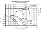
The datasheet specifies the output impedance implicitely by giving the gain versus load resistance, apaprently in a 5 to 10 ohms range. It should be considered when calculating the series termination.

I presume that a buffer amplifier with feedback will give better linearity and more stable gain for 1 MHz signal frequency.

It's true that a single side termination (either source or load side) can suppress reflections, at least theoretically. Double side termination may be preferred for lower gain ripple, though.
 
If your mile of cable is perfect, no joins, no discontinuities, then in theory the mismatched source drives the cable, and all the power is completely absorbed by the load at the far end, because there, it is perfectly matched.
Thylacine is quite correct in that, and you get to claim your +6db prize.

However... if its not a perfect system, and there are impedance humps and bumps, anything reflected back at the source along the way, is going to be reflected with a vengeance back down the cable to the load.
There will be a delayed echo opposite in phase to the original signal.

It might all work perfectly well, there is no real way of knowing for sure without some testing.
.
What I would do, is get my hands on a TDR (time domain reflectometer) and test that cable.
If its as smooth as a babies bum all the way, you can then be almost certain it will work with a mismatched source.
If there are any reflections, you can measure the db return loss, and the time delay will tell you the distance to the discontinuity.

At least then you will know if there are going to be any reflected echoes and how far down they will be in db.

I can have the cable TDR'ed; I assume that it's imperfect though. There's at least one "splice" in it... pretty sure it was about 150ft too short, so the last 150 is an extension.

The datasheet specifies the output impedance implicitely by giving the gain versus load resistance, apaprently in a 5 to 10 ohms range. It should be considered when calculating the series termination.

I presume that a buffer amplifier with feedback will give better linearity and more stable gain for 1 MHz signal frequency.

It's true that a single side termination (either source or load side) can suppress reflections, at least theoretically. Double side termination may be preferred for lower gain ripple, though.

Gain_and_Phase_v_Freq_and_Load.PNG

I hate to ask you to spell something out, but I'm confused as to how you arrived to 5 to 10 ohms from that chart?

Looking at the separation @ 20 MHz, of approx -2.5 dB and -4.5 dB for 100 and 50 ohms, respectively, I calculate out approx. 35 ohms of output impedance, but below that?
 
Last edited:

I didn't refer to the gain versus frequency characteristic.

The datasheet specifies a typical gain of 0.9 with 67 ohm load which gives Rout = 6.7 Ohm.
 
Status
Not open for further replies.

Similar threads

Part and Inventory Search

Welcome to EDABoard.com

Sponsor

Back
Top