Continue to Site

Welcome to EDAboard.com

Welcome to our site! EDAboard.com is an international Electronics Discussion Forum focused on EDA software, circuits, schematics, books, theory, papers, asic, pld, 8051, DSP, Network, RF, Analog Design, PCB, Service Manuals... and a whole lot more! To participate you need to register. Registration is free. Click here to register now.

Power Transfer in Multiple Secondary TRF

Status
Not open for further replies.

pawan kumar

Member level 4
Member level 4
Joined
Jan 31, 2012
Messages
73
Helped
5
Reputation
10
Reaction score
5
Trophy points
1,298
Location
Chennai
Activity points
1,894
Hi Friends,

I accept that the law of conservation of energy can never go false. I got this doubt, if answered, many like me may get benefited.

Consider the image below, Case 1: 10W is transferred ideally agreed.
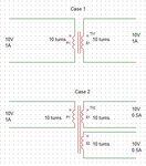
Transformers.JPG

In case 2, is there any way magnetically to prove that since the power input = power o/p, the current gets halved?

What if there is another secondary winding close by... How can the coils understand that and divide current accordingly?

Has this something to do with Mutual inductance? if yes, please guide me on where to read further..

Pawan
 

When you apply load to a secondary, its effect is to try to LOWER the flux in the core, lowering the back EMF generated in the primary winding and causing more current to flow in the primary as more voltage appears across the primary winding resistance.

So yes, you can prove such a thing. For an ideal transformer the flux in the core is proportional to the sum of the products of the turns and the currents in each winding, and the back EMF is proportional to the flux * number of turns.
Assuming equal numbers of turns and eliding some annoying constants (Because electromagnetism was a lot of years ago, and I cannot remember the appropriate magic):

So: Flux is proportional to Iprim - Isec1 - Isec2.
V is proportional to flux.

Hence with a constant voltage applied to the primary, Iprim must equal the sum of the secondary currents, as the applied voltage is constant implying constant core flux.

Obviously real transformers have resistance and iron losses, as well as all sorts of other infelicities, any good EM text book will go into details of the maths.

Regards, Dan.
 
Status
Not open for further replies.

Similar threads

Part and Inventory Search

Welcome to EDABoard.com

Sponsor

Back
Top