Continue to Site

Welcome to EDAboard.com

Welcome to our site! EDAboard.com is an international Electronics Discussion Forum focused on EDA software, circuits, schematics, books, theory, papers, asic, pld, 8051, DSP, Network, RF, Analog Design, PCB, Service Manuals... and a whole lot more! To participate you need to register. Registration is free. Click here to register now.

DC-DC converter isolation, questions from a newbie.

Status
Not open for further replies.

David_

Advanced Member level 2
Joined
Dec 6, 2013
Messages
573
Helped
8
Reputation
16
Reaction score
8
Trophy points
1,308
Location
Sweden
Activity points
12,236
Hello.

I have little experience with DC-DC converters, in designing my own lab power supply I have begun learning but so far all I have worked with is non-isolated non-synchronous buck converters. I do find the isolation of other designs most tempting and interesting but they seem like a huge leap from the step-down converters I've gotten my head around so far and I have a couple of questions.

Would it be possible to isolate the output of any buck converter by using a coupled inductor instead of the usual inductor used in the main LC output filter?

I'm reading about Forward, Push-pull, Half bridge and Full bridge but its unclear to me which would be the most suitable to begin with. Can anyone of them be said to probably be easier to implement than others?

Regards

- - - Updated - - -

Oh, I should say that the converter that I wish to design would have a input of 230VAC and two equal outputs of 40VDC that can deliver at least 3A each.

When using a regular buck converter I could use it as a pre-regulator that maintains a small voltage over a adjustable linear regulator. Could I use a isolated converter in the same manner or does a isolated converter need to be set to a fixed output voltage?
 

Hi,

You say you need two outputs with 40V. Then a flyback is a good solution. But you cant regulate the outputs independently.
Then alway one output is regulated, but the other follows somehow. The second output voltage is not that exact.

Therefore if it is ok for you that both outputs have (about) the same voltage use flyback.

If not - then use independent flyback circuits. If possible synchronize both flyback circuits.
Otherwise you may expect some interference of each other and you will see regulation errors.

Klaus
 
  • Like
Reactions: David_

    David_

    Points: 2
    Helpful Answer Positive Rating
Okey so now I got a basic knowledge of how a flyback converter works, there is however a few aspects that is unclear to me.

I have been searching for a suitable PWM control IC and I find designs and ICs that specify that the output voltage needs to be between 3.3V and 24V or some other voltage range, but that seem strange since I should be able to set any voltage I want through the transformer turns ratio?
I also don't understand what limits a IC to a certain wattage when it uses a external switch.

But I have identified TOP262 as a suitable control IC, its family's datasheet have a 150W 19V @ 7,7A output design that uses a lower power variant of the control IC(TOP258) and I don't see why this would not be a good design to change to a 50V @ 5A output instead with TOP262. I have not jet decided but I might go for 50V instead, and the plan is to design two converters to get two controlled output voltages.

TOP262 datasheet:
https://www.mouser.com/ds/2/328/tophx_family_datasheet-7037.pdf

It will take me some time to get through this datasheet but it appears really promising I think, but it would be a first if the first identified IC in a hunt for parts would in the end will suit my designs needs.
 

Hi David,

Have you tried to read some good reference books on this? Try to get a quick review on those:

Power Supply Cookbook - Marty Brown 2nd ed.
Switching Power Supply Design - Abraham L. Pressman - 3rd ed. (my favorite)
Switch-Mode Power Supply Handbook - Keith H. Billings
Transformer and Inductor Design Handbook - MacLyman (for magnetics, my favorite)
Troubleshooting Switching Power Converters A Hands-on Guide (general tips, all the other have too)
Power Electronics Introduction - Marty Brown
Handbook of Transformer Design Applications - Flanagan (for magnetics too)

Take a look at pressman book and based on your specs you can identify which converter is best. In a first analysis I would say a forward converter (it is like a buck converter isolated) or a flyback.

Regarding the controller, if you go to the flyback converter (which might be the best choice, for power ratings < 500W), from the quick search I did, you can try the UCC1809-1/-2UCC2809-1/-2UCC3809-1/-2 from Texas Instrument. The maximum duty-cycle is 70%. However, on these books, some of them I think have some design examples where they present some controllers that can be used.

Regards.
 
  • Like
Reactions: David_

    David_

    Points: 2
    Helpful Answer Positive Rating
Hello.

Thanks nice books, I have read from two of them and will look into the others sooner or later.
Though I have begun trying to do some calculations and my inexperience gives me obstacles behind every single corner, for example:
δmax = maximum duty cycle, μs
In the text I am currently taking the equations from they are designing as a example a converter with:
Vinput = 85 to 132 VAC
Voutput = 5VDC @ 10A = 50Watts
Frequency = 100kHz
Assume δmax = .45(Okey.... What does that mean for me?)

My converter is rather something like:
Vinput = 207 to 241 VAC
Voutput = 55VDC @ 5A = 275Watts
Frequency = 100kHz(sure, why not)
Assume δmax = 0.??(should I toss out 100 coins in my room and count each head as 0.01 and sum them together to get my δmax?)
Can anyone tell me a acceptable number to use for maximum duty cycle?

I do not look forward to the core selection, selecting the core is by far the biggest challenge for me in the hole design(if I don't have a very very nasty surprise regarding something else unknown to me). I thought that I would post all my calculations in the hope to get help with a sanity check of the numbers, I have begun searching for independent math courses where I live to upgrade my knowledge, Math is my enemy which is very unfortunate seeing as my interests are what they are, electronics.
 

Okey so know I get where the duty ratio comes from, however one thing is bugging me.
when I read about flyback design procedures they often talk about average output power and it makes it look as the output power is a very important aspect of the design, but my design is for a lab supply which means that the output power might be very low while the max output power will be 275W.

Does that create any problems?

I mean is it a problem operating a flyback converter far below the designed average output power?

- - - Updated - - -

Okey so know I get where the duty ratio comes from, however one thing is bugging me.
when I read about flyback design procedures they often talk about average output power and it makes it look as the output power is a very important aspect of the design, but my design is for a lab supply which means that the output power might be very low while the max output power will be 275W.

Does that create any problems?

I mean is it a problem operating a flyback converter far below the designed average output power?
 

Can anyone tell me a acceptable number to use for maximum duty cycle?

A good duty cycle for a flyback is normally 50 % on, 50 % off.
The magnetic flux has sufficient time to build, then collapse, in both states.

You have some leeway where you can increase duty cycle, but it will eventually reach a point where you do not gain anything.

Obviously it is easy to reduce duty cycle.

It is important to design your transformer with the proper step-down ratio, which will accommodate your spec voltage ranges, both supply V and output V. This may not be easy to do.

I mean is it a problem operating a flyback converter far below the designed average output power?

Power transformers have just the right parameters, so that the primary draws small current when the secondary is drawing a small load. They have a lot of know-how in their construction, which we take for granted. That kind of knowledge, if you can apply it, will help in constructing your own transformer.

If your load is light, then your control circuit needs to be smart enough to detect it, and to decrease duty cycle so that less current is drawn from the power supply.
 
  • Like
Reactions: David_

    David_

    Points: 2
    Helpful Answer Positive Rating
Hi,

Try to get 50% duty cycle at full load. If i remember right, then half the duty cycle gives a quarter in output power.(squared relationship)
There is a point of power with a minimum duty cycle in your controller. Below that the controller does not work continously anymore. It will work in burst mode or pulse skipping mode. To avoid this you could connect a minimum load to the output. Maybe 0.5W or so.
But with variable output voltage a simple resistor may not be a good solution.

Klaus
 
  • Like
Reactions: David_

    David_

    Points: 2
    Helpful Answer Positive Rating
I see, I am looking at different controller ICs and some have features like reduced frequency at light loads and such. At the moment TOP261 or TOP262 looks good, the have a lot of different configurations and features to use and the enable me to use a integrated switch while enabling power levels up to 333W. The datasheets at:
https://ac-dc.power.com/sites/default/files/product-docs/tophx_family_datasheet.pdf
but its rather extensive but in any case I like to include it while mentioning any work in regards to a IC.

As for that minimum load concern, I suppose a constant current source would be appropriate. One which can operate with above 55V.

I have taken a easy path for the transformer design using Magnetic Inc's 'Selecting a Distributed Air-Gap Powder Core for Flyback Transformers':
https://www.mag-inc.com/products/se...-air-gap-powder-core-for-flyback-transformers
design procedure in which you calculate primary inductance and peak current and use those two numbers as LI² together with Magnetic's charts in order to look up required core. I have thought to use a toroidal core made out of there 'Kool Mu' material, they offer a E type core as well but no bobbin:( but the toroidal form do offer less impact on surrounding circuits.

Using there guidance in core selection I'm left with using ether there next largest core or there largest core, I am tempted to go with this choice seeing as I am facing some more rather in depth subjects to tackle aside from the transformer and all associated details.

Or perhaps its more like one more subject, that of feedback.
It would appear that in order to proceed(given that the core selection will work) I need to have a actual circuit for the feedback(which I don't).

I will think about and read more about feedback in flyback's and then return here.

Regards
David
 

Please forgive the laziness of this post, I had written a large post explaining things but the website had... I don't know but it all was lost and I am at the limit for what my concentration can handle so I'll just right it very short, I think that help on a site such as this needs to be let us call it 'earned' with a proper investment of your own time and really try to solve it by your self and not just ask to get answers without trying, and I have not been lazy but my ADD limits me and I'll just ask for what I am looking for without showing any work as been done.

The TOP26X design is discarded and I need to choose between using one of the UCC38C4x family devices which is in SO8 package, enbales easy synchronization of my two converters and it has a simple design to implement a flyback converter.
Or to use one of the UCC2851X family devices which would require a larger more complex design for the converter in hole as well as a more complex synchronization scheam BUT then also gain a easy way to implement a PFC converter to feed the flyback converter since those chips are made to do them both at the same time. UCC2851X Offers more options and costumazation as well.

What do you think? do I need a PFC stage?
If I don't could my other equipment at home be disturbed by my dual flyback?
I think I should go with UCC2851X and don't be lazy...

Then comes feedback, making a non-isolated buck converter follow a linear regulatrs output to maintain a small dropout voltage over that linear regulator does only take a couple components. Could a similar circuit be used to feed the feedback circuit to use the flyback as pre regulator?

I have read that to use the TL431 feedback circuit with success I must, MUST measure the loop gain which I can't due to lack of equipment. Is it a simple matter to use the opamp error amplifier type and just hock that up to a optocoupler?

Regards
 

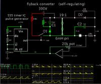
Here is a simulation which portrays operating concepts in a flyback. The scope traces are invaluable to get a grasp on what's going on.

It has voltage self-regulation (somewhat). The load voltage is monitored by an op amp, which alters voltage at the 555's control pin. This makes duty cycle shorter or longer, as produced by the 555.

It has not been tested with real components.


The analog switch is a 'gimmick' component available in the simulator. It gives the appearance that the primary side is isolated from the secondary side.
 
  • Like
Reactions: David_

    David_

    Points: 2
    Helpful Answer Positive Rating
David, as this is your first attempt at something like this, I would work up to it gradually.
Just start out initially with one single 40v output flyback supply.

The first thing would be to decide between using a single switching mosfet, or build the half bridge diagonal topology using two mosfets.

The half bridge diagonal circuit, although requiring extra parts has one supreme advantage. The flyback voltage across the mosfets is hard clamped to the incoming dc supply voltage, and this eliminates mosfet destroying over voltage spikes.
Its a much safer (for the mosfets) circuit.

Second suggestion would be to design it for a 20Khz switching frequency, not 100Khz. Its a lot more forgiving, especially with regard to winding the transformer and physical layout.

Third suggestion, use a gapped ferrite core, not a powdered iron toroid as you suggested earlier. The air gap allows you to adjust the inductance, which you will definitely need to do to get it working properly.

Fourth suggestion, use a current mode control chip, something that has cycle by cycle current limit, that plus the half bridge diagonal topology makes the circuit pretty much indestructible.

Don't bother with a secondary winding, or feedback at this initial stage, you can add that later. just control the duty cycle directly with a potentiometer, and monitor the current in the primary to get a good idea of what is going on.

You can run it up to full power like that !
All the stored flyback energy just recirculates back into the large dc input capacitor. Once you can wind that up and down with your duty cycle control potentiometer, add the secondary to the transformer, and test that into a suitable load resistor.

Once that part is working too, you can then add voltage feedback to it, and do some transient load testing for optimum dynamic performance with step load changes.

Its all a matter of one step at a time, getting each part to work properly, then adding a bit more to it.
It will all be great fun, and very instructive.
 
  • Like
Reactions: David_

    David_

    Points: 2
    Helpful Answer Positive Rating
I like your suggestions and I have taken a break from the flyback design doing other fun stuff, but now I have gotten away from the subject in order to return hopefully keeping to a better more calm approach.

My next challenges are finding a controller that allows me to build a half bridge diagonal circuit flyback circuit while synchronizing two such converters, you did suggest cycle-by-cycle current limit capability. But I find more peak current controllers while I have not been able to find or understand the biggest pros vs cons of these two current control scheams.
There name do explain what or in what frame the limiting is performed but what that does mean for me and the circuit functionality that is a big ? for me, but when you suggests one kind I assume there are reasons why you believe that that's the one most suitable in my application. finding the right one with all I want/need is not easy.

The synchronizing seems to perhaps be a problem but I am not talking about implementing it now but I do not want to get a controller that does not allow for synchronizing to be implemented since later on that will be a important point of the design.

Then the inductor-transformer, I see your point about adjusting inductance. But from what I have read Kool Mu(Sendust) powdered cores does have the benefit of smaller leakage inductance and such a core lacks the uncertainty of inductance that ferrite offer. The inductance of a coil on a ferrite core has a error marginal that can be quite wide as I understands it and that marginal have multiple contributors while a Kool Mu have non worth speaking of so I want to ask your opinion about implementing a Kool Mu core transformer in a EE style? Then I can add a air-gap... But maybe that is not a good idea.

I believe that Continuous Conduction Mode(CCM) is my aim and I do know that I can choose between CCM and Discontinuous Conduction Mode(DCM) by adjusting the inductance of the inductor-transformer as low inductance will result in DCM while high inductance will result in CCM. But what is the implication of that right-half-plane-zero that CCM adds to the transfer function?
And I don't get the implication of the 'output diodes reverse recovery problems' though that I shall research more.

The transformer will need to be able to deliver 275W max, 55V @ 5A. How much a overhead is proper to design with?
Could you say that the fact that CCM adds a DC bias to the inductor-transformer that the full wattage of a core can never be utilized for power delivery to the output?

As I see it right now I would guess that I would do well in designing a converter to operate in CCM at higher loads, say over a range of 25% to 100% output current(or is it 25-100% output power?) and then let the thing operate in DCM below 25%. Is that how you do(can do) it?
To be honest I do get confused when looking closer at how that should work when it comes to turns ratios and how the output voltage is or is not a function of that, I hope that it will make sense sooner or later but any clarification would be appreciated.
Actually I guess that in asking about things I am more looking to get advice on how to do it rather than to understand it and by that I mean that as long as I can get far enough to be able to implement the first stage I can answer most things my self by studying and trying things out for real which is the best way to learn I think. I perceive a difference such that I can read or be told that it works this way and that way but the only way for me at least to get a real understanding which include a intuition of sorts is to play with the hardware and find out by doing.

It will all be great fun, and very instructive.
This had stopped being fun, but your approach sure will be.
Thanks.

And thank you all for your inputs.

Regards
 

If you have definitely decided on the half bridge diagonal topology, you will need a suitably isolated gate driver for the upper mosfet.

Something like an IR2110 is a very common approach to this.
As both mosfets switch on and off together, you drive both inputs of the IR2110 from one of the two outputs of your PWM controller. That gives you the required 0% to 50% duty cycle.

Synchronizing two PWM controller chips is easy.
You hook up the timing resistor and timing capacitor to one chip so it works normally.
Then connect the timing capacitor pin of controller number two to the timing capacitor of controller number one.

Both chips then share the exact same timing ramp developed across the one timing capacitor. its not really synchronization as such, but direct slaving off the one ramp oscillator.

The Kool Mu cores are available in a whole wide range of permeability for a reason.

You calculate the required number of turns from Faraday's law, to get the desired flux swing in the core at the voltage and frequency you are using.
The inductance you end up with is then a bit of a lucky dip.
It is calculable if you have the right magnetization curve though.
But final in circuit measurement often ends up being a little bit different.

If the inductance ends up being way different to what you require, you get to do it all again with a different permeability Kool Mu core.
You will definitely get something usable after a couple of attempts, but it is really doing it the hard way for a one off project.

With ferrite, you calculate your required turns in the exact same way, and then experiment with an air gap.
It takes about one minute to get the inductance spot on very first attempt.

For a Lab bench supply, it will sometimes have to run with zero load, so full energy transfer mode is unavoidable under very light loading.

Likewise at a low set output voltage, and full max current, continuous mode operation is unavoidable.

Its very different to designing something that runs all day continually fully loaded at a fixed output voltage.

If you do decide to use gapped ferrite, you can very easily adjust the inductance, and the changeover point between the two modes of operation.

As this is a home project, and you are not planning to manufacture thousands of them, you can afford to over design it and use a decent sized core, maybe double the conventional size, and then have absolutely no fears about saturation or overheating, or running out of grunt.
 
Last edited:
  • Like
Reactions: David_

    David_

    Points: 2
    Helpful Answer Positive Rating
I have never used IR2110 or similar so that will be fun, and you've convinced me to go with ferrite.

Funny thing, in "Switchmode power supply handbook" they have a full chapter dedicated to a 'SWITCHMODE VARIABLE POWER SUPPLIE' which is a .... Half bridge diagonal flyback converter 300W who's output is 0-60V:)

Switchmode Power Supply Handbook 3/E

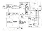
The chapter begins at page 440 but here is a picture of the circuit concept:
supply_concept.png

Later in the book there are complete schematics, I will try and quickly describe the setup in its operation but its very much new info so I will certainly fail to include all important notes. But to begin with it operates in DCM(or more appropriately complete energy transfer mode) at output voltages of 30-60V and in CCM(incomplete energy transfer mode) below 30V. When Warpspeed used those terms I did not get them but now when I do I do prefer them since they much better describe what is happening then using CCM() and DCM(). so with a output voltage of 30-60V the full 300W is available and below 30V the output power will be reduced and finally at 10V or below the output power is limited to only 200W. I believe that this has to do with wanting to keep the cores flux density constant and always have an equal volt-seconds amount.

The tricky part is that this setup will need to switch between constant frequency mode and it has to do quite a lot of different things, I might be wrong but I think I counted up to 5 different mode of operation over the hole range of output voltages/currents. And the controllers I have looked at so far does only offer one or two of these modes, but I am still looking.

There are more to say about the setup but I'll stop there, I guess I plan to copy the functionality of there circuit but using circuit blocks as IR2110 and some PWM controller. I find it very hard to only focus on the first steps of the outlined plan without at least considering how the next steps should be implemented. Man I had not anticipated that this would need to be so complicated but I find this subject to be very entertaining to working through.

Though I have to remember to take in account for conditions such as no load and 0V thought 0V is not needed as some voltage can be dissipated in my linear regulator/bjt post-regulator stage.

I don't know if I am asking anything in this post or just trying to reduce the confusen I experience, I do feel that this project is coming along nicely. I can at least see that there are and end to this flyback stuff and as soon as I have done some more detailed investigation about the transformer needed I will order a pair together with the needed components to implement the first step in the design.
But I think I should at the same time order some other stuff that I can be sure will work since I need to order for a certain amount to avoid making the purches to expensive through shipping costs(no cost for shipping above some amount of $$$).

The books design is at chapter 24, chapter 25 is a short chapter about the transformer needed so I feel very lucky indeed to have the same goal in mind as they had.

Regards
 
Last edited by a moderator:

Man I had not anticipated that this would need to be so complicated but I find this subject to be very entertaining to working through.
Its complicated because the good Mr Billings decided to design a "dream machine" with every conceivable desirable feature expected in high quality commercial product.

For example, you could have two or more switched output voltage ranges in your own design.
One covering the high voltage end, the other (using a different secondary winding) to cover high current low voltage side of things.

It would simplify things greatly.
But if you want to control the output voltage continuously from 0 to 60v with a single knob, then it all becomes a whole lot more challenging.

Your best bet might be just start off with a primary winding, and manually control that with a potentiometer. That part is not too complicated as the mains supply voltage is more or less constant.
Just so the primary power is controllable from zero up to XXX watts.
That part of the design then becomes pretty well fixed.

Just about all of the difficulties arise with the secondary, and the very wide range of both voltages and currents it must cater for. The primary duty cycle has a practical operating range, which often falls rather short of what is required.

The alternatives are either Billings style complexity, or something a bit less elegant, that works just fine for your own requirements.

When you size your core, make it a big one !
It will then leave you plenty of physical space to experiment with high current or multiple secondaries.
 
  • Like
Reactions: David_

    David_

    Points: 2
    Helpful Answer Positive Rating
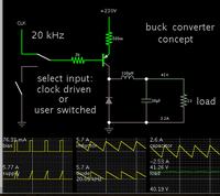
I've realized my flyback simulation (post #11) is a lot to grasp. It's only a still image.

I have one of a buck converter, which can serve as a simple tutorial. It's animated and interactive.


Falstad's simulator is capable of creating a weblink (see below). Clicking it will:

1) Open the falstad.com/circuit website,
2) Load my schematic into the simulator,
3) Run it on your computer.

https://tinyurl.com/nfyfl2h

This is an animated, interactive simulation. Electrons (or rather current bundles) travel through wires at a speed proportional to the Ampere level. Scope traces move across the screen.

Switches respond to your mouse clicks. Watch the waveforms that result from the tempo of your clicks, or, let clock pulses drive the action.

Alter values at will. Right-click on a component and select Edit.

- - - Updated - - -

It's a Java applet, so you need Java installed on your computer. If the link does not work, there is no doubt a workaround.
 
  • Like
Reactions: David_

    David_

    Points: 2
    Helpful Answer Positive Rating
I have on more than one occasion gotten access to this falstad.com simulator which appears a great tool for learning however I continually struggle with enabling Java on my browser but I can't get it running.

I will address the subject raised about complexity of the suggested(by me) circuit but first I have a concern about the core.

For the suggested circuit they used a core PM 87 with a Inductance factor(Al) of 12µH, they say that this core is rated for 800W and that this type of circuit requires a more powerful core than one would normally need. And I though "Great, that core should be a good fit for me as well" but before even getting into the details I was chocked by the price.
78USD!

Is it that I am just not aware of how expensive ferrite cores are or is this a extra fancy core?
Would an equivalent sized core in EE style cost as much as this PM core?

I would love to have such a PM core with its shield property's but that price is not something I will pay while smiling.

I find it hard to follow Warpspeeds suggested step-by-step plan, in that that I will do as suggested and get the primary side working first but I can't feel good about doing that without at least a thought about whats will come next.

Or I can re-think it all and be prepared to get the primary side running in order to learn and then change the hole design to cater the secondary needs.

Does it get simpler if one goes from designing for 0-60V to 10-60V(10-55V actually)?

I have not in this thread showed what project this came from but I will shortly post a image of what I have had in mind.

- - - Updated - - -

Would it bring any relieve in complexity if I don't care about the power output being constant and can accept 5A at 55V and 5A at 10V?
Or is that just stupid in a case such as this?
 

There are a great variety of ferrite cores to choose from, and above some minimum limiting size, any of them will work.

Make absolutely sure you can get a plastic winding bobbin, preferably several if possible. They are not expensive, just terribly difficult to source in small quantities in most cases.

If you ask, the supplier says sure we have them in stock, twenty cents each, no worries, minimum order one thousand pieces......

Usually its a lot more difficult trying to source just one or a very few bobbins than the ferrite core that goes with it.
It would be a pity to buy an expensive pot core or EE core, and not be able to use it because there are no bobbins available. Its truly a big problem for prototyping or one off home construction.

The flyback topology only drives the core in one direction magnetically, so you only get to use one half the BH curve, and therefore need double the number of turns.
Something suitable for 1Kw in a push pull, or bridge circuit only gets you roughly half that operating in flyback mode for a given core volume.

There are also some interesting problems fabricating very high current windings as far as skin effect go, and just using big fat wire is not the answer.
You will have far fewer problems at 20 Khz than at much higher switching frequencies, and that also means a pretty bulky core.

Pot core and E core sizes tend to stop at about the sizes we are interested in, and U cores start at about that size (maybe 500W and up).
Ease of winding is another attraction of a UI combination.
Just remove the I, and wind straight onto the middle of the U, and you don't really need a plastic bobbin. Then just fit the I with whatever air gap you need, and you are in business.
There will be a ton of room for your experimental windings.

Funnily enough I was looking for a big UI core just yesterday for my own future high power flyback project.
Some of the prices quoted were truly shocking, but one company "Dexter magnetic technologies" were quoting prices only a fraction of what some other suppliers are asking for the exact same part.
I have not bought anything from them yet, only discovered them yesterday, but they are definitely worth a look, and they sell online.
 
  • Like
Reactions: David_

    David_

    Points: 2
    Helpful Answer Positive Rating
Okey I will be very determined to follow the step-by-step approach so I will now only concern my self with controller features I want, and order all other needed parts for the primary. Maybe I need to write a "must have" list for finding a controller.

Now I am just throwing stuff out there.

1, synchronization to other controller possible.
2, current mode control.
3, cycle-to-cycle current limiting.
4, adjustable duty cycle.
5, adjustable dead-time.
6, around 20kHz frequency

Those might be good to have, I am reading but still have no over view of what kind of controllers are avaiable on the market but I'll just keep looking and sooner or later I'll have a grip on that.

Oh and the core choice is one big To-do, I'll check out that company.

Regards
 

Status
Not open for further replies.

Similar threads

Part and Inventory Search

Welcome to EDABoard.com

Sponsor

Back
Top