Continue to Site

Welcome to EDAboard.com

Welcome to our site! EDAboard.com is an international Electronics Discussion Forum focused on EDA software, circuits, schematics, books, theory, papers, asic, pld, 8051, DSP, Network, RF, Analog Design, PCB, Service Manuals... and a whole lot more! To participate you need to register. Registration is free. Click here to register now.

[SOLVED] [HELP] OP-AMP Using LM324

Status
Not open for further replies.

darrylcapulla

Junior Member level 1
Joined
Dec 15, 2014
Messages
19
Helped
0
Reputation
0
Reaction score
0
Trophy points
1
Location
Pili, Camarines Sur, Philippines
Visit site
Activity points
145
I want to make an OP-AMP using LM324 - QUAD OP-AMP.
Input is 50mVolts & out is 10Volts so the Gain is 200.
1st op-amp is for Buffer.

My question is, should i use all three remaining op-amps?
Or should i use only one ?

Please answer thanks :)

lm324.JPG
 

The datasheet for the lousy old LM324 shows that when its gain is 200 times then its frequency response drops above only 2kHz so sounds will be more muffled than an old telephone or an AM radio. Also it is very noisy and has crossover distortion.

For amplifying DC then the maximum input offset voltage of 7mV will cause an output of plus or minus 1.4V with a lot of noise when there is no input voltage. The offset of 1.4V will be added or subtracted to/from the expected output voltage.
If an opamp is a non-inverting amplifier then it has a high input resistance and does not need a buffer. An inverting amplifier has a fairly low input resistance that might need a buffer.

Since it has 4 opamps then the unused opamps should be properly disabled to prevent oscillation.

Why not use a better modern single opamp instead?
 
What is the application?

What device is the signal coming from? And what device is the signal going into?


@audioguru if his profile location is correct he is in a remote part of the Philippines where there is very limited access to parts.
 
the signal comes for a Signal Generator or test with mp3 player.

This op-amp is connected to a push-pull amp, with 6.125 watts output and input of 7volts peak-coming from op amp.

Parts is not so limited, we order it in Manila or buy it online, i choose LM324 because its easy to solve and this op-amp uses only 2 resistors :D

True, some of my classmates used this, it is very noisy. The Distortion, - clear found in the oscilloscope :D

what modern single op-amp should i replace with this one? :-D
can u suggest some?
there are many opamps, but idont know which should i choose. please help

**broken link removed**
 

It's not impossible to use LM324 for audio applications, but some points have to be considered.

- Gain-bandwidth-product is about 1 MHz, the bandwidth with gain of 200 would be only 5 kHz
- LM324 has class B output stage which generates large distortions if not biased in a suitable way
- input stage voltage noise doesn't suggest usage with low-level sources, e.g. microphones

To achieve acceptable bandwitdh, the gain of 200 must be divided into at least two stages of lower gain. The LM324 output stage must be forced into class-A operation by a pull-up (or pull-down) resistor to overcome crossover distortions.
 
Hi,

look for audio OPAMPs.
They usually have an AB output stage, have low offset voltage and low noise. Look for enough GBW

Gain of 200 calls for a high gain bandwitdth or a two stage system.

for two stages with equal gain you need sqrt(200) = 14.14 for each stage (giving about 70kHz for the LM324). Maybe more gain in the first stage.

*********

Noise also depends on source impedance.
For high impedance source: OPAMPS with FET input stage are better (lower noise current)
for low impedance source: OPAMPS with BJT input stage are better (lower noise voltage)

To get an "optimum" a lot of calculations are necessary and reading a lot of OPAMP datasheets...

Klaus
 
what modern single op-amp should i replace with this one? :-D
The TL071 is not very modern, but it is good for audio (and general purpose), is cheap, and is easily available (even in through-hole packaging).
TL072 is the dual version, TL074 is the quad version.
Datasheet is here.

As FvM mentioned, it's a really good idea to split the gain into two stages e.g. one opamp with a gain of 20 followed by another with a gain of 10. That not only improves the bandwidth, but it also reduces distortion a lot. It doesn't cost much extra since the single, dual and quad opamps are all about the same price, so you just need two extra resistors.

Good luck!
 
the signal comes for a Signal Generator or test with mp3 player.
This op-amp is connected to a push-pull amp, with 6.125 watts output and input of 7volts peak-coming from op amp.
Parts is not so limited, we order it in Manila or buy it online, i choose LM324 because its easy to solve and this op-amp uses only 2 resistors :D
what modern single op-amp should i replace with this one? :-D can u suggest some?

I can not open your attachment.......
Lucky you now that you can order online. In the old days I had to go to Quiapo [in MetroManila].

Do you have a dual power supply? Or just single-ended [V+ and ground]? You can use a conventional op-amp in a single-ended power supply but it is a bit more tricky.
Not sure about the 10mV input - sounds very low if coming from a MP3 player or signal generator.
Vout also sounds high - more a current booster than a conventional amplifier.

I looked here https://ph.rs-online.com/web/c/?searchTerm=audio+op-amp&sra=oss&r=t
Good selection of op-amps but could not find a convenient link to the corresponding datasheet.
The NE5532 is something of a classic. and 'hindi mahal'
JFET op-amps [like the TL071/2/4] have a very high Zin, but you don't need that. I have heard reports they can be unstable.

What is most important to you?
Frequency response - look for best Gain Band Width
Noise - look for lowest noise figure
Distortion - look at higher end audio op-amps
Transient response - look at slew rate
Budget - look at the price!

As stated you will probably want to split the gain over 2 op-amps, so you will likely prefer a dual op-amp.
 
JFET op-amps [like the TL071/2/4] have a very high Zin, but you don't need that. I have heard reports they can be unstable.
During my entire career designing and building audio circuits, I used thousands of TL071, TL072 and TL074 from American manufacturers. They all worked perfectly and none failed.

I saw a notice from a Japanese manufacturer, I think it was Toshiba who introduced "better" TL07x audio opamps, but their production was stopped when they found out they all oscillated.

I agree that a signal of only 10mV is much too low to come from an MP3 player. It is probably 25 times higher.

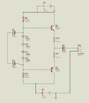
I think the students are making their own audio power amplifier. The opamp is the gain stage and the output is push-pull made with a complementary pair of transistor emitter-followers producing an output of 6.13W into 8 ohms that has a peak-to-peak output swing of 19.8V and needs a power supply that is about 26V. Its input level will be 7V peak when it is barely clipping.
 

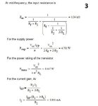
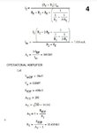
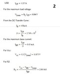
Here's my computation and schematic diagram. Im using 400k for resistor feedback and 30k- R1.
We use dual power suppy. :-D
can u please check my solution?? thanks!!

1.JPG2.JPG3.JPG4.JPGcap1.JPGCapture.JPG

- - - Updated - - -

As FvM mentioned, it's a really good idea to split the gain into two stages e.g. one opamp with a gain of 20 followed by another with a gain of 10. That not only improves the bandwidth, but it also reduces distortion a lot. It doesn't cost much extra since the single, dual and quad opamps are all about the same price, so you just need two extra resistors.

Good luck!
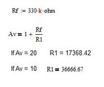

What values should i set Rf or R1?
If i use 20 gain and 330k for Rf i'll get R1 = 17368.42, and for gain of 10, R1 is 36666.67
should i assume higher Rf values or lower?
22222.JPG
 

Students have found on the web and posted that awful circuit on this forum many times. Nobody makes an audio amplifier like that.
As the input voltage rises then the input current into the output transistors decreases instead of increasing. It causes distortion. There is no negative feedback from the output to reduce the distortion.
1) Audio amplifiers are DC coupled from input to output. Yours is not.
2) Audio amplifiers have negative feedback from the output to the inverting input but your output stage has no negative feedback.
3) Opamp A and opamp D do nothing and can be replaced with a wire. The input from the volume control can feed opamp B and opamp C can feed the output stage. Then only 2 opamps are needed. An LM358 has two of exactly the same lousy opamps that are in the LM324 and its case has only 8 pins.
4) The 1N4001 rectifier diodes are for high currents and are slow. They poorly match the low current diodes in the darlington transistors. Use 1N914 or 1N4148 little low current diodes instead that are fast.
5) Your emitter resistor value of 1 ohm is extremely high and will cause less output power into a speaker than you want.

If the feedback resistor value is too high then stray and input capacitance at the inverting input of the opamp to ground will cause increased gain at high frequencies.

A sounder is a piezo whistle, isn't it? Don't you want to use a real 8 ohm speaker?
 

Actually i don't know what my Teacher really wants us to do. I don't really know if its a audio amp or what.
All i know is, this circuit is connected to a Function Generator - as Vi source of 50mV at 1khz.
1st Stage is op-amp using TL074 , gain of 200 and Vout of 10Volts.
Opamp A - He call this a Buffer, we need to included that ,are teacher said that, even its just non-sense i think. hahahaa :D
2nd stage is for Power-amp, output power of 6.125 watts, Speaker used is 8ohms.

This "awful circuit " i don't design it, he just gives this to us then changes the values and computation. Im just following orders :D

Sounds like Dog whistle. hahaha

what values should i use for op-amp resistor feedback?
 

Hi,

maybe the task for this exercise is to build a really bad audio circuit... with the challenge to improve it.

As audioguru said: nobody would build an audio circuit like that. Not the circuit nor the OPAMP, nor the resistor values, nor the output stage.

OPAMP "A" here has no benefit. It just acts like a additional noise source and distortion source. And worst of all the noise and distortion is amplified by the folowing stages.
OPAMP "D" is useless in any way.

All the elctrolytic capacitors in the output stage should be special unpolarized audio types.


You say you do just what your teacher told you.
I really hope your teacher uses this circuit as an example of bad development ... and uses it to do some noise and distortion measurements and shows you how to improve the circuit.


Klaus
 

One of the coupling capacitors feeding the output stage has backwards polarity. Can you find which one and correct it?
Did you see the crossover distortion produced by the lousy old LM324 opamp on an oscilloscope? It makes a buzzing sound and it looks like this:
 

Attachments

  • LM324 crossover distortion4.PNG
    LM324 crossover distortion4.PNG
    52.3 KB · Views: 247
Status
Not open for further replies.

Similar threads

Part and Inventory Search

Welcome to EDABoard.com

Sponsor

Back
Top