Continue to Site

Welcome to EDAboard.com

Welcome to our site! EDAboard.com is an international Electronics Discussion Forum focused on EDA software, circuits, schematics, books, theory, papers, asic, pld, 8051, DSP, Network, RF, Analog Design, PCB, Service Manuals... and a whole lot more! To participate you need to register. Registration is free. Click here to register now.

How can I make this with optocoupler ? analog input and digital input

Status
Not open for further replies.

fateme91

Member level 2
Member level 2
Joined
Nov 18, 2014
Messages
48
Helped
2
Reputation
4
Reaction score
2
Trophy points
18
Location
Iran,Mashad
Activity points
349
Hi
I need to schematic this circuit with an atmega16 :

8 npn analog input with opto
8 npn analog output with opto + transistor
4 digital input (2 ones 0~10 v and 2 ones 4~20 mA)
2 digital output (1 ==> 0~5 v and 1==> 0~10 v)
1 serial port RS232 and 1 port rs485

Can u Help me??
 

Makes no sense. The words "analog" and "digital" are apparently interchanged in your specification.
 

Hi
I need to schematic this circuit with an atmega16 :

8 npn analog input with opto
8 npn analog output with opto + transistor
4 digital input (2 ones 0~10 v and 2 ones 4~20 mA)
2 digital output (1 ==> 0~5 v and 1==> 0~10 v)
1 serial port RS232 and 1 port rs485

Can u Help me??

I guess the specification should be like this,

8 npn digital input with opto
8 npn digital output with opto + transistor
4 analog input (2 ones 0~10 v and 2 ones 4~20 mA)
2 analog output (1 ==> 0~5 v and 1==> 0~10 v)
1 serial port RS232 and 1 port rs485

Then it is clear and easy to understand.
 

Sure

You'r right. I made a mistake.... !


I guess the specification should be like this,

8 npn digital input with opto
8 npn digital output with opto + transistor
4 analog input (2 ones 0~10 v and 2 ones 4~20 mA)
2 analog output (1 ==> 0~5 v and 1==> 0~10 v)
1 serial port RS232 and 1 port rs485

Then it is clear and easy to understand.

- - - Updated - - -

Tnks ... but there is not complete answer .


- - - Updated - - -

I don't underestand what does it mean?

4 analog input (2 ones 0~10 v and 2 ones 4~20 mA)
2 analog output (1 ==> 0~5 v and 1==> 0~10 v)

How can i make it? Please help me....
 

4 analog input (2 ones 0~10 v and 2 ones 4~20 mA)

There are four analog input channels. Two of them will get analog voltage signal in the range of 0 to 10v. As your ADC input range is 0 to 5V, so you need to reduce the 0 to 10v signal to 0 to 5V range. You can easily do it using two resistor by making a resistor divider network.
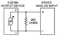
Other two of them will get analog current signal in the range of 4 to 20mA. As your ADC only can read voltage, so you need to convert current signal into voltage signal. Using a 250 ohm resistor you can easily convert the 4 to 20mA current signal into 1 to 5v voltage signal, which will then go to ADC input. See the picture below


Also read about 4-20mA current loop here https://www.murata-ps.com/data/meters/dms-an20.pdf

2 analog output (1 ==> 0~5 v and 1==> 0~10 v)

There are two analog output channels. One will give 0 to 5v output and another one will give 0 to 10V output. For analog output you need DAC. Your microcontroller does not have any DAC. It has only digital output pins as outputs. So to get analog output, you can use PWM technique on any digital output pin, then after RC filtering and OPAMP amplification you will able to get desired analog output. For 0 to 10V output see the picture below

 
There are four analog input channels. Two of them will get analog voltage signal in the range of 0 to 10v. As your ADC input range is 0 to 5V, so you need to reduce the 0 to 10v signal to 0 to 5V range. You can easily do it using two resistor by making a resistor divider network.
Other two of them will get analog current signal in the range of 4 to 20mA. As your ADC only can read voltage, so you need to convert current signal into voltage signal. Using a 250 ohm resistor you can easily convert the 4 to 20mA current signal into 1 to 5v voltage signal, which will then go to ADC input. See the picture below


Also read about 4-20mA current loop here https://www.murata-ps.com/data/meters/dms-an20.pdf


There are two analog output channels. One will give 0 to 5v output and another one will give 0 to 10V output. For analog output you need DAC. Your microcontroller does not have any DAC. It has only digital output pins as outputs. So to get analog output, you can use PWM technique on any digital output pin, then after RC filtering and OPAMP amplification you will able to get desired analog output. For 0 to 10V output see the picture below


Thank you so much. It's very complete and helpful. But...
in picture (2 ones 4~20 mA) what does it mean "output device" ? which device i should put here?

I appreciate so so so much...
 

But...
in picture (2 ones 4~20 mA) what does it mean "output device" ? which device i should put here?

this box means a tranducer that produces constant current as an output which ranges from 4 to 20 mA. You will then connect a resistor and then at any instant , you can measure the voltage drop on this resistor through ADC. Once you know the voltage, you can get the instantaneous current by using Ohms' Law I=V/R;
 
this box means a tranducer that produces constant current as an output which ranges from 4 to 20 mA. You will then connect a resistor and then at any instant , you can measure the voltage drop on this resistor through ADC. Once you know the voltage, you can get the instantaneous current by using Ohms' Law I=V/R;


Tnks.. I underestand the circuit. which transducer u mean? What is the Input of this picture?
I know the output connects the ADC of micro.
 

transducer = sensor..

sensor converts a physical quantity to an electrical quantity (i.e. voltage and/or current and/or change in resistance)

thermocouple is a sensor... senses temperature and generates voltage. Strain Gauge is a sensor, it senses pressure and its ressitance changes... like wise, There are some sensors that convert physical quantity into 4 to 20 mA current output.
 
2.jpglll.jpg
transducer = sensor..

sensor converts a physical quantity to an electrical quantity (i.e. voltage and/or current and/or change in resistance)

thermocouple is a sensor... senses temperature and generates voltage. Strain Gauge is a sensor, it senses pressure and its ressitance changes... like wise, There are some sensors that convert physical quantity into 4 to 20 mA current output.


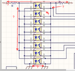
I made it in Altium designer as U said . when i want to update pcb this error accures. What does it mean and what can i do ?
 

Before you start any design, define your requirements like any logic and isolation required.
0 = __V max
1 = __V min
Then you can determine worst case CTR of photodiode/transistor after aging ( not typ.) ( Often 0.3 to 1)
Then you can caclulate using Ohm's Law on current limiting resistors.

You get no benefit on optoisolators if the in/out supply & Gnd is the same source.
optoi.png
 
yes sunnyguy is right.... the optocoupler is used to isolate the input from output... if you make the supply common then optocoupler is useless you could have used a transistor instead. Otherwise, you should separate the optocoupler input supplies.
 
I made changes. The error "mach nets" accures again. what should i do ?
 

Attachments

  • 1.jpg
    1.jpg
    322.5 KB · Views: 124

There are four analog input channels. Two of them will get analog voltage signal in the range of 0 to 10v. As your ADC input range is 0 to 5V, so you need to reduce the 0 to 10v signal to 0 to 5V range. You can easily do it using two resistor by making a resistor divider network.
Other two of them will get analog current signal in the range of 4 to 20mA. As your ADC only can read voltage, so you need to convert current signal into voltage signal. Using a 250 ohm resistor you can easily convert the 4 to 20mA current signal into 1 to 5v voltage signal, which will then go to ADC input. See the picture below


Also read about 4-20mA current loop here https://www.murata-ps.com/data/meters/dms-an20.pdf


There are two analog output channels. One will give 0 to 5v output and another one will give 0 to 10V output. For analog output you need DAC. Your microcontroller does not have any DAC. It has only digital output pins as outputs. So to get analog output, you can use PWM technique on any digital output pin, then after RC filtering and OPAMP amplification you will able to get desired analog output. For 0 to 10V output see the picture below


I'm sorry for my a lot questions..
can u tell me why we use RC fitering?
 

The PWM wave is a sum of DC and AC voltages. The DC voltage component is average voltage of the wave which is equal to Vp*D [Vp is peak voltage(5V for atmega16) and D is duty cycle]. Controlling the duty cycle from the software we can control the amplitude of the DC voltage component. We want this DC component as analog output. A low pass filter blocks AC signal and let DC signal to pass. So a RC low pass filter is used to get only the DC component out as analog output.
 
Status
Not open for further replies.

Similar threads

Part and Inventory Search

Welcome to EDABoard.com

Sponsor

Back
Top