samna_asadi
Junior Member level 3

Follow along with the video below to see how to install our site as a web app on your home screen.
Note: This feature may not be available in some browsers.


Optos have very poor CTR tolerance, so no good for precise regulation, without complexity of mirror feedback loop.


Hi,
to be more linear and equal for both LM317 i recommend to transmit the setpoint as PWM with optocouplers.
As PWM generator you can use a NE555, or ucontroller.
On the output side you need low pass filtering.
1% linearity error should not be a problem.
Klaus
Hi!
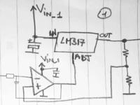
If you don't want to use uC or digitals, and you want to control multiple LM317 with one pot, you can put for each LM317 the out pin connected to a voltage divider (2 resistors in series), then connect the middle point to the inverting input of an OPAMP, and the out of the opamp to the ADJ pin of the LM317. the out of the pot should be connected to the non-inverting input of all the opamps.
Choose the pot and the opamp in a way that the bias current does not affect the set point of the potentiometer, and that the opamp out can sink the current coming from the ADJ pin. You can also buffer the output of the pot as well.
The schematic you proposed is absolutely not isolated, incredibly non linear, and this means that it doesn't work as you may think. The best way to make it "linear" is to use PWM (as suggested by KlausST).


**broken link removed**
As you can see from the picture it a very basic, simple schematic...
Some adjustments should be done, depending on the components that you want to use, precision...
if something is not clear, or you think that is wrong, please ask


But unfortunately not working. The fact that it's inverting the polarity of LM317 feedback should be a sufficient indicator.As you can see from the picture it a very basic, simple schematic...


