Continue to Site

Welcome to EDAboard.com

Welcome to our site! EDAboard.com is an international Electronics Discussion Forum focused on EDA software, circuits, schematics, books, theory, papers, asic, pld, 8051, DSP, Network, RF, Analog Design, PCB, Service Manuals... and a whole lot more! To participate you need to register. Registration is free. Click here to register now.

100nF capacitor charged up to 30V will damage LED array?

Status
Not open for further replies.
T

treez

Guest
Newbie level 1
Hello,
We are designing a led driver, spec = vin=30vdc, vout=19vdc, iled = 2.5a

If somebody disconnects the led load, then the output capacitor (100n) gets charged up to 30V….Then when someone re-connects the led load, the 30V , 100n capacitor suddenly discharges through the 19v led array….will the led array be damaged?….the energy is 0.5.C.V1^2 – 0.5.C.V2^2

Where C = 100n
V1 = 30V
V2 = 15V

So total energy = 33.8uJ…….though what does this do to the led array?….will it weaken it , incidiously, making it fail in the field prematurely?


the mlx10803 led driver we are using doesn't facilitate open led protection, (at least not without many extra components)......but we stay using the mlx10803 because it is the only one that jitters the switching frequency......we need this because there are 24 of these cards inside the enclosure, so we need the jittering , or else we will get ticking on the supply ...which is two PSP-500-24 PSUs.....each supplies 12 mlx10803 driver cards.
 

If you say the stored energy is 39µJ from a 100nF cap, what is the time duration and ESR&ESL of load?

Let me make some assumptions to estimate these. The ESR is 1Ω per watt per device.(Tony's rule of thumb)
You have a 50W array something like 6S4P using 2W per LED for 6x3.7V for 22Vnom.
Thus 2Wx24 LEDs, 6S4P, ESR=6*½/4=0.75Ω .
Or.. 1Wx48 LEDs, 6S8P,ESR=6*1/8=0.75Ω.

Your array may be different. Let's use 1Ω.
Thus we can approximate the surge duration as T=ESR*C=1*100nF=100ns (neglect ESL)
So 39 µJ=W-s =>390W in 100ns or about 8x your 50W nom. Power (19V*2.5A)

Although Cree do not specify a max surge, it is a poor design practice because gold wire bond is the weak link , which can partially sheer open from poor thermal design and process control in soldering, which degrades the mechanical margin above If max, which means they could fail open. Also hot-plug lights is a major risk for ESD damage <-5V per LED. Therefore a good design needs protection for all of the above.

this is just an approximation as LED drops ESR with rising surge power, T reduces and I increases until V=Ldi/dt limitations.
 
  • Like
Reactions: treez

    T

    Points: 2
    Helpful Answer Positive Rating
If you will be making a lot of these lights then when you ask Cree about this surge problem they will be happy to tell you the max pulse current and duration.
 
  • Like
Reactions: treez

    T

    Points: 2
    Helpful Answer Positive Rating
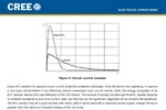
This is what Cree suggest and I agree is the preferred solution. The Imax stated in the spec is what they guarantee.
image.jpg
Unlike non-optical components, to reduce visibility, the thinnest shortest smooth radius goldwire bond is attached which gives much less margin (undefined due to customer solder stress) than a power diode which can be pulsed 100x its average rated current.
 
  • Like
Reactions: treez

    T

    Points: 2
    Helpful Answer Positive Rating
The peak current handling capability must be related to the active volume of the LED chip. I assume there's no risk of damage with µJ or even high mJ energy levels and any usual power LED.

You have a different situation with laser diodes or e.g. GHz transistors with pretty small active volume. They can be damaged by rather small energies and sub-µs pulses.
 
  • Like
Reactions: treez

    T

    Points: 2
    Helpful Answer Positive Rating
Have you ever seen the wire in a fuse flex when its circuit is powered? It breaks due to metal fatigue even when it is never overloaded.
I think the bonding wires in an LED will break the same if they do not burn out first. The white hot bonding wire might produce more light than the LED.
 

true. I think this is all about the slenderness and extreme delicateness of the bonding wires in leds, and how they cannot take even the most short duration overcurrent transients...I now wonder whether the 100n will indeed produce a damaging discharge current in the led.....those bonding wires are just so severely fine in leds.
 

I reviewed a number of applications notes related to EOS (electrical over stress) of LEDs but didn't find a single remark about possible effects of sub-microsecond surges as discussed in this thread, except for ESD pulses. The discussed protection means, e.g. in the CREE application note quoted in post #4 are always dealing with inrush currents in the ms time scale.

Bond wire current handling can be calculated as fusing I²t. The discussed pulses are several orders of magnitude below it.
 

You wont find any of my reports on the web. But Cree suggest below...
Based on the 1-KHz pulse testing we have reviewed in this application note, cree suggests the following guidelines for pulsed current operations:
1. For duty cycles between 51-100%, do not exceed 100% of the maximum rated current;
2. For duty cycles between 10-50%, do not exceed more than 200% of the maximum rated current; 3. For duty cycles less than 10%, do not exceed more than 300% of the maximum rated current
and these are two distinct failure modes.

ESD fails in the reverse direction, but wounds often go undetected. It fails at extremely low power >|-10V| and >50uA typically depending on jct size.

Ratings are always -5V, leakage specs range from 1uA for yellow, red to 10uA for small blue, white.

Surge failure occurs in the forward direction, which is stressed by all forms, shock, vibe, heat thermal shock, excess peak solder duration, and craters created by ESD.

Both often fail at or near the wirebond.


I speak from 1st hand knowledge dealing with customer induced thermal stresses that sheared bond wires. Also ESD issues , both which caused $200k rejection of one shipment of tunnel instaled products in Switzerland 6 months after installed from one project with a few early failures.

I have dealt with dozens of preferred factories for LEDs on these issues out of hundreds to pick from at one time in Taiwan.

As a result , all products in the last 8yrs, that I purchase have ESD protection and some had double ultrasonic wirebonds per pad for enhanced shear strength. All these parts are custom made to my specifications.
 

Yep, I can confirm 'SunnySkyguy' Exp.

Get a drain load on the capacitor, a protection zenner or atleast a small SMT resistor , also you MUST have ESD protection on consumer LED products.

We had a number of LED product designed by a 'genius' designer, failure rate was ~18%.
I redesigned the products with protection around the LED arrays, failure rate dropped to less than 1% within several months of introduction with further reductions.

New LED really have to be treated with kid gloves.
Mis-handling inside the bonding operation or even mis-configuration of the bonding machines and weld force, is enough to completely destroy your company due to loss from failures in the field.

I even have prepared reports on defective lead-frames causing significant field failures, due to internal stresses.

Our business was worth over 20 million $ to the final market, so again, we were not selling a few led product.
 

If there is a C 1000nf on the load side, Which will get charged from the 100nf cap for 3V of discharge of 30V. before the LED turns ON.
 

It is buck led driver, low side fet....output cap is only one 100nF
 

Why the driver and LEDs are removable ? Are they compatible with some other LED loads?
What if the cap is in the LED side ?

Buck convertor with low side mosfet, Is LED connected between +Ve terminal and drain ?
 
  • Like
Reactions: treez

    T

    Points: 2
    Helpful Answer Positive Rating
Sticking my neck out here: I think the chances of damage from a single 11V overvoltage pulse from a 100nF capacitor are extremely slim. The situation isn't reverse voltage or high voltage discharges, just a small capacitor discharging into a low impedance with the energy dispersed through several LEDs. Even the impedance of the wiring/capacitor is going to lessen the chances of damage.

I am not suggesting it is safe to continuously pulse LEDs this way or that ESD precautions should be ignored but in this instance the risk is extremely low.

A zener diode across the LEDs or even another larger capacitor across them would fix the problem, as would a bleed resistor or Zener on the PSU side. Even a ferrite bead on the LED side might be enough to smooth the pulse.

Brian.
 
  • Like
Reactions: treez

    T

    Points: 2
    Helpful Answer Positive Rating
As FVM indicated the fuse effect of I²t must be considered and in most cases, I agree 100nF discharges very quick.

So let's calculate the stress for the 1-10µm gold wirebond after 400 deg solder thermal and EOS stresses are applied.

Since this is stochastic in nature, merely testing one that passes the test, does not certify all.

As Cree calmly stresses in their Youtube videos, never exceed the absolute maximum current for any reason.

however a simple solution is to put 100nF on the LEDs then a capacitive divider cuts the voltage in half, absorbing all the energy. But your PWM might not like it, so an ICL is ideal.
 
  • Like
Reactions: treez

    T

    Points: 2
    Helpful Answer Positive Rating
I might add, a few years ago in Toronto, I was looking for scrap metal to fix a gate and found a supplier with a big box of MCPCB's populated with Cree 3W LEDs. most had 18 per board for 12 to 48Vdc inverter for Ambulance flashing lights.

These are what I used in my Avatar ... Ceiling lights powered by a modified 65W Lappy charger.

Every board was scrapped from at least 1 defect by a local assy shop (possibly Solectron)

These are 100% process EOS/EOT failures, not bad parts. I salvaged most of them worth about $10k in BOM cost for a scrap purchase price of the aluminum of $20. Just use them for myself and friends.
image.jpg The wound effects of EOS/EOT often manifest as lower Iv intensity and intermittent wirebond joints.
 
  • Like
Reactions: treez

    T

    Points: 2
    Helpful Answer Positive Rating
You CANNOT use just an SMD ceramic ML capacitor as a way to arrest ESD, it will possibly be the biggest mistake you will make.

Also check on your driver circuit is the 100n capacitor an SMT version rated at 25 volts? it could be you are only seeing 30 volts max, because the dielectric is leaking.
 
  • Like
Reactions: treez

    T

    Points: 2
    Helpful Answer Positive Rating
You CANNOT use just an SMD ceramic ML capacitor as a way to arrest ESD.
I'm unable to find this idea in the present discussion. To which post are you referring particularly?
 
  • Like
Reactions: treez

    T

    Points: 2
    Helpful Answer Positive Rating
I'm unable to find this idea in the present discussion. To which post are you referring particularly?

I thought that was the way the discussion was going on a number of fronts as regards capacitors,?

however a simple solution is to put 100nF on the LEDs then a capacitive divider cuts the voltage in half, absorbing all the energy. But your PWM might not like it, so an ICL is ideal.

A zener diode across the LEDs or even another larger capacitor across them would fix the problem, as would a bleed resistor or Zener on the PSU side. Even a ferrite bead on the LED side might be enough to smooth the pulse.
 
  • Like
Reactions: treez

    T

    Points: 2
    Helpful Answer Positive Rating
Status
Not open for further replies.

Part and Inventory Search

Welcome to EDABoard.com

Sponsor

Back
Top