Continue to Site

Welcome to EDAboard.com

Welcome to our site! EDAboard.com is an international Electronics Discussion Forum focused on EDA software, circuits, schematics, books, theory, papers, asic, pld, 8051, DSP, Network, RF, Analog Design, PCB, Service Manuals... and a whole lot more! To participate you need to register. Registration is free. Click here to register now.

Tell me your advices for my PCB Layout please

Status
Not open for further replies.

kaSva

Junior Member level 1
Joined
Nov 26, 2013
Messages
19
Helped
0
Reputation
0
Reaction score
0
Trophy points
1
Activity points
136
Hello,

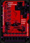
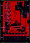
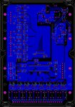
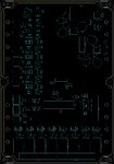
I designed a layout and i wanna your comments/advices/recommendations for my layout? Thank you for your help

Schematic (pdf):
View attachment vgs2000-schematic.pdf

Images:
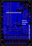
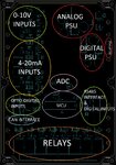
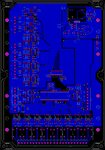
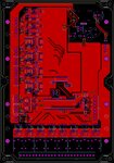
vgs2000-bottomcopper-bmp.jpgvgs2000-topcopper-bmp.jpgvgs2000-topcopper-bmp.jpgvgs2000-bottomcopper-bmp.jpgvgs2000-placement-bmp.jpgvgs2000-placement-bmp2.jpg
 
Last edited by a moderator:

Maybe i just missed it, where do you connect those three different grounds?
 
Overall it's looking quite well planned & laid out, I have a few comments though.

You have opto's for some reason, and you have a nice big isolation gap underneath them.
Then you totally ruin this clearance on the RH side where the copper pour comes a lot closer to J13 and you come back with components to the other side of the opto.

So I guess its not for any HV isolation purposes.

How small are those vias? They look to be very small, very small costs more, I'd make them bigger with bigger pads seeing as you have the room :)

If you move some of the angles on the tracks under U16 (top elec) you can join the grounds together.
I see no stitching vias to join the grounds. **

At the bottom of R4, R11,R55, U27 etc you have an acid trap.
IMO Rotate D22\D23 etc 90 degrees anti clockwise or move the cap along side it.

c65\c66 move to top side so they are inline with the track not shooting off it.

Bottom elec - the ground under U16, if you look at it - it only has a single very thin connection above U7.
The mitred track above R76 can be mitred some more to allow the copper to flood through a lot thicker. **

Is U8 going to need a heatsink? if so move the caps a bit further away. Whats going on with the ground not going into it fully?

At the least I'd do those marked **

It's always worth spending a little more time going through a PCB criticizing it yourself so that you can find those little things that will make it better.

BTW - its in an enclosure\box, how the heck do you propose to connect wires into the terminal blocks with them being so close to the walls of the enclosure?
Grab everything from J14\14 up to the optos and move them all up as far as you can get them, consider the wires going into the connectors. - Unless they are a plug in thing...?
 

Having separate analog and digital grounds primarly raises the question how they are related and what's the ground reference of signals crossing the boundary. The fact that you have apparently connections across it without an accompanying ground, e.g. in the ADC/CPU area makes be wonder if you are doing something really bad.

Generally, we need to review the schematic, also to understand the relation of digital and relay ground.
 

@FvM so what are you recommend to me? My english is not enough please tell me simply.
 
Last edited by a moderator:

@Mattylad thank you very much for your detailed interesting. I reply you late because, I noted your recomendations and i applied to my project. So i wanna ask you some questions? (My english is bad please answer simply)

1-) "I see no stitching vias to join the grounds. **" What you mean here?
2-) "At the bottom of R4, R11,R55, U27 etc you have an acid trap." What you mean here?

BTW - My terminal block is vertical plug type
 

Your "analog" and "digital" supply are isolated against each other, but you have a SPI bus between both regions. That doesn't work.

My suggestion is simple: Join the analog and digital ground to a continous ground plane, save one DC/DC converter and 5V switcher, use separate power supply filtering and decoupling for both supplies.
 

Hello i updated my layout. Can you tell me your advices again?

@FvM i did your advices please check

bottom.jpgtop.jpgasd.JPG


You must have at least a low impedance (not through a ferrite bead) connection between analog and digital ground along with the SPI bus. My suggestion was to join both ground planes completely.
 

Hello,

I designed a layout and i want your comments/ advice/ recommendations for my layout? Thank you for your help

Schematic (pdf):
View attachment 109940


- Grounds have large slots which make good antenna to Relay transient noise coupled nearby. Use star grounds from DC source not serial ferrite connected. Use Star output DC, not serial sequential filtered.

Why do you have PN for 5V relays on 12V power?, I am be concerned about thermal loss on 12V Relay power if all active 400mW x N since LDO has 24Vin

Many other DFM issues in layout.
 

Status
Not open for further replies.

Part and Inventory Search

Welcome to EDABoard.com

Sponsor

Back
Top