Continue to Site

Welcome to EDAboard.com

Welcome to our site! EDAboard.com is an international Electronics Discussion Forum focused on EDA software, circuits, schematics, books, theory, papers, asic, pld, 8051, DSP, Network, RF, Analog Design, PCB, Service Manuals... and a whole lot more! To participate you need to register. Registration is free. Click here to register now.

PIC microcontrollers... the chip has to be powered independently for programming?

Status
Not open for further replies.
Hi,

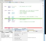
Just to add on to that long video, you can see in this pic how to add a Breakpoint so when you use the Simulator and Debug then it will advance to the Breakpoint line and then stop waiting for you examine registers as shown in that vid or to Step or Go to the next breakpoint if your chip can do more than one.

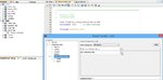
You can also use the Debugger Stopwatch function to check the timing on your various delay and loops etc.
 

Attachments

  • 000117.jpg
    000117.jpg
    78.7 KB · Views: 81

I think my modus operandi for now will be to simulate the program in the Simulator, debug it that way, and then download it to the chip and cross my fingers it works. I did run into some issues today where it appeared that the IDE wasn't seeing my #include command. It was giving me errors upon trying to build it where it seemed to think that my status, trisa, trisb, etc. were undefined. Upon poking around the internet, I found someone mention that you should include a "udata" directive before any registers you define yourself, and then a "code" directive when you are ready to start the program code. Just putting those two words in cleared up all the errors and the project built. That made me think "Man, I really need to sit down with the IDE user's guide (all 274 pages of it) and really figure this out. But a quick search for the term "udata" turns up nothing. What voodoo have I invoked here?

Also, I'm now beginning to feel like there is a special "place" for what you type into the editor. One, I feel, should not put a directive in the first column, as that is reserved for labels. Again, this was never mentioned in the Wilmshurst book I'm reading... what other norms is one expected to follow when entering code as it pertains to the columns?


Hi,

With Assembler you have 2 distinct ways to create/compile your code, Relocatable and Absolute.

Seems by default X goes to the Relocatable option, I would suggest you change it to Absolute code as shown in the pic below.

As you can see, my code / include line built ok in the default relocatable mode, don't know how you typed your code ?
Udata and Code are relocatable instructions so I suggest you remove them for Absolute mode.

As for which bits of code can start in line 1 etc, no need to go searching into for books or manuals, just go into the Help menu where there is a host of sections for MPASM.

If you want some working code for say a led flasher to give you something to work from then just say what chip you are using and we can post you and example.


No matter how basic your code is, post it if you are having problems, then we can see what needs putting right, we all started off the same...;-)
 

Attachments

  • 000118.jpg
    000118.jpg
    83.8 KB · Views: 74
  • 000119.jpg
    000119.jpg
    94.5 KB · Views: 76
ah, that's where the absolute mode button is. so after MUCH pecking around in MPLAB X, I was able to simulate my program. I wanted to use the timer0, and I figured out that you have to set up a clock stimulus to get it to work... pretty proud moment there when the tmr0 register started displaying something other than what I had loaded it with. I think the reason my code wasn't building was I had put the org 00 statement in the wrong place and it was skipping some important stuff. Derp! anyway... here's the result:

https://www.youtube.com/watch?v=qtthaR8utho&feature=youtu.be

Hi,

Looks really good :cool:

Also good to see someone still using standard logic chips, after using those you really understand the circuit and appreciate how much a micro can do.
 

Hi,

Just had chance to look at that Wilmshurst book on Pics seems quiet comprehensive , however a couple of tips for your coding to make thinks easier.

The use of Directives when changing Banks ( and Pages in advanced coding) can make things a lot easier.
Also the use of directives for specifying your user variables.

code example below
Code:
;       progam to flash all of PortB pins on and off every 4 seconds


		list p=16f84a
		include p16f84a.inc

                __CONFIG   _CP_OFF & _WDT_OFF & _PWRTE_ON & _LP_OSC
                            ; using 32k crystal as the main oscillator (LP)

		cblock 0x0C		  ; specify user regiaters starting at location 00x0C
		d1,d2,d3                ; work fields for the delay routine
		COUNT
		endc


		org 	0x000
		GOTO	Main


Main	CLRF	PORTA		; Set porta & b to digital outputs
		CLRF   	PORTB

		BANKSEL TRISA       ; select the relevant bank
		CLRF	TRISA
		CLRF 	TRISB
		BANKSEL 0           ; return to bank 0 


LOOP					; main program looP
		CALL	DELAY4s		; call this subroutine
		MOVLW   0xFF
		MOVWF	PORTB		; Set  port HIGH

		CALL	DELAY4s

		MOVLW   0x00
		MOVWF	PORTB		; Set  port LOW
		GOTO	LOOP


;  SUBROUTINES

DELAY4s		          ; 4 SECOND DELAY
                            ; created using the routine from
                            ; http://www.golovchenko.org/cgi-bin/delay
        movlw	0xFF
        movwf	d1
        movlw	0x19
        movwf	d2
Delay_0
        decfsz	d1, f
        goto	dly1
        decfsz	d2, f
dly1    goto	Delay_0

        return

		END		; END OF PROGRAM CODE
 

Status
Not open for further replies.

Part and Inventory Search

Welcome to EDABoard.com

Sponsor

Back
Top