Continue to Site

Welcome to EDAboard.com

Welcome to our site! EDAboard.com is an international Electronics Discussion Forum focused on EDA software, circuits, schematics, books, theory, papers, asic, pld, 8051, DSP, Network, RF, Analog Design, PCB, Service Manuals... and a whole lot more! To participate you need to register. Registration is free. Click here to register now.

need concert a constant current inverter 140 amps in a constant voltage inverter.

Status
Not open for further replies.

kees52

Junior Member level 1
Joined
Jul 31, 2009
Messages
15
Helped
2
Reputation
4
Reaction score
2
Trophy points
1,283
Location
the netherlands
Activity points
1,422
Hi There

I want build a weld inverter, but need it for mig only who needs a constant voltage supply.

Now I have find a 3 - 60 volts supply with current adjustment (limit) from 0 to max 40 amps.

It is the same topology a forward converter, I do use of the supply only the pwm chip uc3845
who is also in the current source welder.

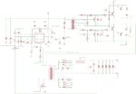
Can someone give me some advise, I include the schematics.

regards

kees shema.gif
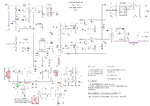
Here is the source of voltage feedback and current set. I think with this I can even when disconnect
voltage feedback I have a current source alone so can weld stick or tig. (tig need output caps removed/ ac?)
do the current limiter shut of the whole smps or keeps it just on that max current? is so I have a constant current source.

http://danyk.cz/reg60v_en.html

thanks for the help, I need some shure to have it right, it seems not all to difficult, voltage feedback is
just an extra error opamp who howver sit already in uc3845 and sg3525, last chip is also better for two
outputs.

welder has to be adjustable from 8 to 34 volts max 140 amps.

regards

kees
 

Although your schematic appears to be a complete project...

and the linked article contains ample explanations...

and it is made up mostly of ordinary components...

It is a complicated project, carrying several kilowatts.

There are a couple of transformers. These must be constructed just right, if you are to be successful. It looks as though you need to scale up their size from that described in the article.

The project has several sections, which must interact correctly, or else the output will go wrong. You can build the project, but you should also look forward to troubleshooting one or more sections.

It may be better to start with the most basic conversion circuit, and get that working. Then install the adjustment sections, regulation sections, etc.

do the current limiter shut of the whole smps or keeps it just on that max current? is so I have a constant current source.

Current limiting keeps it on max current.
 

Thanks for the reaction.

I have not build it yet, I am a experienced electronic man do amplifiers, tube/mosfet hybrides at most.

I now these smps supplys are not tools, I do start with the low supply sections, test them with a scope
for signals and also use a bulp or os for the big work.

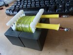
I have not much difficult with winding a trafo or make litzwire for it, I have E71/33/32 core ready.

primairy windings are done see picture.

I have in the meantime do some research, I do now now how to implement things like a feedback for
the constant voltage section, it needs however output elco,s to get rid of the ripple otherwise
it will not work, a integrator /opamp is used or the erroramp in the pwm chip.

full bridge is even more difficult because off balance, even when winding the trafo.

I ask myself is it better to use copper strip for the secondairy? I did read it is better for
skin effect.

Thanks for your reaction, don,t be scared I get killed or exploded, I have years of experience
only the math side I am not so good at.

regards

keesDSCN1741.JPG

see picture
 

Hi There

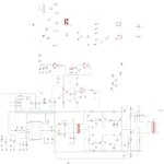
I have drawn and change the welder such that I have a constant voltage, but can also
with some relays do change back to current, and use mma or tig.

Making trafo and such is easy, I can work very precise.

The welder is now made also stronger, more igbt and output rectifiers because of mig welding
who is constant shorts with that wire. I have also made the voltage pot double and use a
setup that will make wire speed faster when give more voltage so I have not to experiment
with wire speed anymore, it is always oke.

see picture of changed schematic, let me now if there can be better updates.

I need a point in schematic where I can put weld pistol switch, for set inverter on and of without
damage or problems because somtimes it is weld on and of quickly, possible a pulser can be used
to puls it on and of incl the wire feed.

thanks

keesinverter test.jpg
 
Your schematic is neatly laid out. It reflects a professional approach. As far as I can tell, it is likely to work.

Nevertheless consider that my words come from someone with no experience with a UC3845, nor other such control IC's.

Questions:

* I think you are giving U$3 (transformer) pulsed DC? Because T1-3-4-5 appear to turn on simultaneously. I understand DC welding is superior to AC welding. Is that the reason you are not sending AC through U$3?

* R15, C6, D13... R14, C2, D14... Are these snubbing networks? Because U$3 appears to see high impedance between current pulses.

* Diodes D15-16-18 are parallel. Also D17-19-20. Will they be matched for V/I characteristic? Because if one diode has a slightly lower fwd voltage than its sisters, it will hog current, and risk burning out.
 

Hi there

It is a forward inverter, igbt,s do turn on simultaneously, it has a deadth time between on turns to prevent
core U3 to get saturated.

The resistors and caps you mention are snubbers, because of the switches cause trouble without them, it is
in all forward inverters.

The diodes are very fast recoverys, I do not now if she get problems because of be parallel, temp rising with equalize them
(like IGBT do) using resistors fro doing this is not a very good idea, all the welders do use paralell diodes or one big 200 amp diode, this
one is still very expensive and a hobbie needs to be cheap if can.

Thanks for the plus about the schematic drawn, I do my best.

Welding AC or DC.

MMA and tig needs AC, MMA cab also be DC, (plus min reversed) and what I use is MIG
this schematic is for the MIG, and needs a clean DC and a constant voltage source, the MMA
and TIG needs a constant current source, both can be made possible.

However the UC 3845 have not a input to set inverter on and off save, but a SG 3525 has
on pin 10 a possibility to do that, so I have drawn also a SG type inverter (forward), this one
comes from a author from poland or Tsjechie, I have use parts of this schematic because of
it has antistick and such, I can weld MMA and MIG with it, it is handy.

regards

keestest-inverter.jpg
 
Hi There

it is long time ago that I have try things like a inverter welder, I have done some things in ltspice
like a soft switch resonant inverter who is quite nice for big range in weld current.

here some sims about it, there are so much possibilities a quasi resonant with a frequentie setup do
very wel is simple and have big range.

And so I do learn some about smps, I do use a comparator for the feedback, normal feedback a la supply
do cause trouble when welding, even blowing the inverter, with soft switching the dead time is very important
you can see this very easely on sim.

regards

kees

feedback oke.jpgfeedback to slow.jpghigh current protection.jpgmaking the loop faster did this.jpgsoft switching;-).jpgScreenHunter_553 May. 21 16.05.jpg
 

Status
Not open for further replies.

Similar threads

Part and Inventory Search

Welcome to EDABoard.com

Sponsor

Back
Top